The intriguing weathering steel form of Cody Dock Rolling Bridge stands among a variety of other creative projects undertaken in recent years at the ex-industrial facility built in 1871. While much of the nearby London Docklands environs underwent vigorous regeneration in the 1990s, transforming it into the financial centre it is today, the former coal-handling area of Cody Dock was dammed up.
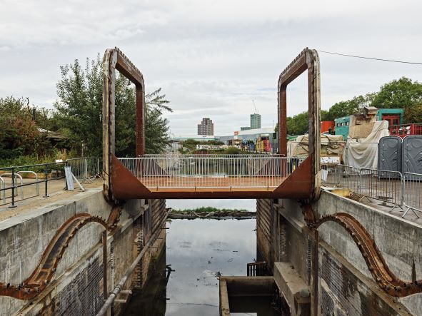
Cody Dock Rolling Bridge in London (GG Archard)
Decades later, with the aim of regenerating the disused area, Gasworks Dock Partnership (GDP) was registered as a charity in 2011 and has since achieved numerous milestones, from cleaning up the surrounding land and developing a creative industries quarter to re-establishing public footpaths to improve access to the dock and the River Lea. Reconnecting the dock to the river and its better-known distributary, the Thames, is an important project goal, and since this required removing the dam, planning was acquired for a movable footbridge.
“They were buying something that was quite standard, off-the-shelf: a Dutch bascule bridge. So I said, ‘Do you mind if I make a counterproposal, because I think you can do something that’s more exciting and something that people come and actually see rather than just walk across’,” Thomas Randall-Page, the bridge’s designer, explains between the western abutment and some raised planting – one of many community-led initiatives on site.
The seeds of inspiration for the concept were sown during a subsequent canal tour, where the charm of the locks, their balanced systems and low energy requirements, encouraged Randall-Page to create something for the dock with similar appeal and functionality. The resulting sketches were of a shallow deck suspended between two chamfered square hoops which could be rolled 180° along abutments into open and closed positions. Opening the bridge would invert the deck from ground level to being upside-down, several metres above the water, providing vertical clearance for boats.
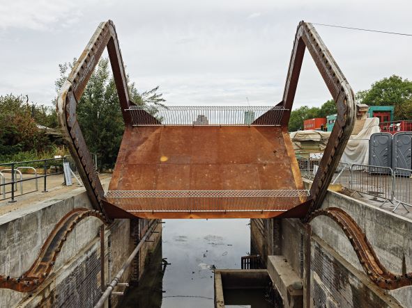
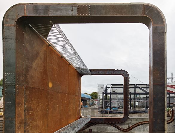
The rolling bridge halfway between open and closed positions (GG Archard)
“I showed my sketches to Tim Lucas [structural engineer] at Price & Myers, and he was really excited about it,” says Randall-Page. Thereafter, a working 1:50 model was built and the design evolved to employ cables to draw the bridge across a pair of undulating steel racks, rather than a pinion and wheel as originally conceived.
The human-powered element of canal lock operation has been cleverly applied to the 13t-heavy bridge via two winches installed at either end of the track on the east abutment: one is used to tension a cable anchored to the top of the eastern portal hoop and pull the bridge along while the other is simultaneously unwound to release the cable on the other side. The bridge is counterweighted using 2.5t of concrete and scrap steel at the top of each 5m by 5m box section hoop, putting the structure’s centre of gravity at their centres. “The idea is that the centre of gravity doesn’t move up and down, it just moves horizontally in a line, and from that generates the form of the track. Because the hoops are square, it’s got these undulations that pick up the corners, and the pins and teeth interface with one another and prevent any skewing, or one side moving faster than the other,” Randall-Page explains.
The calculations and catenary shape needed to move a square were derived from the work of GB Robison in 1960 and Stan Wagon’s square wheel bike experiment in 1997. However, due to the chamfered nature of the corners on the bridge’s hoops, the equation had to be adapted by Price & Myers over the different sections of track to match the changing geometry.
A 5.2m-wide by 7m-long internally stiffened trapezoidal steel deck box is welded to the bottom of the two hoops and accommodates two locking pins to keep the bridge in place when in use. The box tapers in depth from 550mm at midspan to 400mm and 350mm at each end and side, respectively. Galvanised steel balustrades run along the deck edge, and these can be rotated inboard and fixed to the deck surface to provide roughly 0.85m extra clearance when the bridge is open, giving a total vertical clearance of 5.55m from the mean high water mark. Bolted onto the edge of each hoop are 52, 15mm-thick teeth, which interface with 90mm-diameter pins spaced at 350mm between centres along two undulating 15m-long tracks each side of the canal. Hardox steel was selected for the pins due to its abrasion resistance.
Thermal expansion was a key consideration as it had the potential to disrupt pin/teeth alignment (GG Archard)
While all the main structural elements consist of 5-8mm corten steel plate, several materials were considered for the bearing slip, including rubber and different plastics. Wood, in this case oak, was ultimately seen as the best choice given that any worn material could fall into the canal. The aesthetics of the oak as it ages should interplay pleasingly with the weathering steel as it develops its characteristic patina, and the material has the added benefit of being simple to replace and appropriate to the setting of a Victorian-era dock.
To bring the concept to bear as a working life-size structure, Price & Myers started with a model in Grasshopper for Rhino to simulate the translational motion of the object. This was then put into Oasys GSA for most of the initial analysis of stress, deformation, footfall, and frequency. “In terms of parametric modelling, we also used Karamba so we could check the stress and movement in real time during the roll. Based on the span, the stresses weren’t too much of an issue, it’s more just deflection. Since it’s being rolled on one side, there’s quite a bit of torsion in the system; the whole deck is essentially a torsion box,” says Robert Nilsson, structural engineer at Price & Myers.
Parametric analysis of wind action on the bridge was also conducted, with the deck in the half-open/closed position putting it in a particularly exposed position. “We wanted to see with wind and all these forces combined, how much this side [the side that is not winched] twists, which also affects tolerance and potential jamming,” says Nilsson, adding that one of the biggest challenges in realising the design from an engineering perspective was weight. “The more weight in your system, the more friction you might get in the track. Also, if the pins got too big, then the oak packer would get taller, which means the bridge hoops would get longer, and in turn the track gets longer. So it was quite a lot of work just to fine-tune everything.” From their modelling, the engineering team made their best guess of the friction forces they would encounter, knowing that when on site, they would be able to use cables and load cells to check and confirm what they were in reality. For frictional effects and a slightly unbalanced centre of gravity (no wind), the predicted load cell reading was 3kN, while the actual reading was 2.5kN.
David Knight, director of design and engineering at Cake Industries, the project’s steel fabricator and main contractor, also notes that thermal behaviour was a key design consideration given the tight tolerances involved, as with any moving bridge. Indeed, thermal expansion and contraction of the deck had the potential to disrupt alignment between the teeth and pins, which was complicated further by the fact that the underside of the deck would expand more than the top with the bridge in the open position and vice versa with the bridge closed.
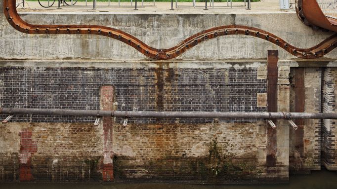 The shape of the tracks was generated by modelling the horizontal movement of the structure’s centre of gravity (GG Archard)
“In our original design we assumed we would weld the whole thing together with an onsite splice,” says Nilsson, “It was David who pushed us to use bolted connections, which in hindsight was good as it allowed for onsite adjustment. If the deck gets too hot, the hoops come in and try to slide off the teeth or jam.” Knight adds, “It’s all minuscule tolerances in comparison to most construction, but the bolt holes are just a bit bigger than the bolts, so you get enough tolerance there to adjust how straight the hoops are and where things land.”
Steel fabrication took place in Cake Industries’ facilities 16km south of Cody Dock, but the tight tolerances made it crucial to conduct thorough checks on site. “A lot of time was spent checking, double checking, rolling and re-rolling the bridge,” explains Knight, with small amounts of steel trimmed off some of the teeth during the process to ensure they were hitting the right pin positions. The oak – which was steam bent by Charlie Whinney Studio in the north of England and bolted onto the hoops – was also trimmed in situ as needed.
In March this year, the bridge was transported to the site in four parts: the top halves of the hoops and longitudinal halves of the deck welded to their respective lower hoop sections. Final assembly and welding of the deck was completed on site, and the bridge was craned onto the tracks by the end of that month. Since Bd&e’s site visit on 15 September, handover has been completed and the crossing is expected to open to the public in November. It currently takes around 15 minutes to open or close, though the team are discussing potential efficiencies to be found through different handle options on the winches. Whether stationary or playfully rolling along, the bridge is quite the spectacle, and despite the highly novel aspects of its form and function, it still manages to evoke the historic fabric of this once-neglected dock landscape – all for a very limited construction budget of just over US$200,000.
All photos courtesy of GG Archard