Bids for construction of the new Ironton Russell Bridge over the Ohio River are due to be invited in November this year. But the designers of the crossing, which will link Ironton in Ohio with Russell in Kentucky, have had to resolve conflicting constraints in order to provide a solution that suited all the parties involved.
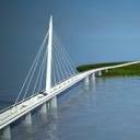
When completed, the Ironton-Russell cable-stayed bridge will be the longest single tower, steel edge girder, cable-stayed structure in North America and one of the longest in the world. The total length of the bridge is 781m and it consists of a 576m-long river crossing with a 205m-long approach on the Ohio side. Design of the cable-stayed structure presented a number of configuration challenges, most specifically the fact that while the agreed location of the new bridge was on a skewed alignment, the navigational requirements stated that the pier substructures should be parallel to the river flow. The width of the navigation channel meant that a dual-tower structure was out of the question. The cable-stay unit consists of a back span of 241m and a main span of 290m and adjacent to the main-span is a continuity-span of 46m.
One of the most demanding constraints was the requirement of the US Coast Guard that any substructure units falling within the 100-year flood elevation must be positioned such that their faces are parallel to the flow of the river. The alignment that had already been chosen and approved for the new bridge forms a 70 degree skew with the flow of the Ohio River. This produces a skewed alignment of 20 degrees at the centre-line of the bridge and any affected river piers. This skew posed challenges to the tower configuration, superstructure supports at the tower and superstructure framing.
As a solution, substructure units in the river were configured with round circular shafts from the top of footing elevation 500 up to elevation 545.5 - the 100 year flood elevation - with tapered pier caps having an elliptical cross-section that would be perpendicular to the bridge centre-line.
The 576m-long crossing could not be designed as a typical dual-tower cable-stay bridge span arrangement due to navigational clearance requirements. The US Coast Guard specified horizontal and vertical clearance requirements for the navigational channel both during construction and after completion.
Using the provided minimum clearance criteria, the initial cable-stay bridge span arrangement would have required a single tower with a back span of 247m and a minimum main span of 274m. However, this span arrangement would not have given optimum efficiency. The key for establishing an efficient span arrangement for a cable-stayed bridge is to develop enough tension in the back stay cables from dead load to offset expected live load reduction. Recent three-span (dual tower) composite-deck cable-stayed bridges typically have exhibited a back span to main span ratio of about 0.42 to 0.46.
By multiplying the span by 1.8, similar ratios may be used for single-tower composite-deck cable-stayed bridges. The initial span arrangement based on using the minimum main span of 274m gave a ratio of 0.5 which did not seem efficient for back span cable tension.
For efficiency of cable tension, the lower ratio of 0.42 would appear to be the optimum, but other issues also had to be considered. Three possible solutions were investigated to reduce the initial ratio 0.5 down toward 0.42.
The first was to keep the 274m main span and move the Kentucky abutment towards the tower by 30m to reduce the back span to 210m. While this would give a desirable ratio of 0.43, it was neither feasible nor practical due to lateral clearance requirements with the railway that runs parallel to the Kentucky shore, and the tall abutment height this would produce.
The second option was to keep the location of the Kentucky abutment and maintain the 274m main span by moving both the tower and pier two by a distance of 30m toward the Kentucky shore. Again this would give a ratio approaching 0.42, but would put pier two into the navigation channel which would violate US Coast Guard requirements.
The third option considered was to hold the locations of both the Kentucky abutment and pier two and move the tower towards the Kentucky abutment therefore increasing the length of the main span and shortening the length of the back span. This appeared as the only feasible approach to reduce the back-span to main-span ratio from 0.5 down to a range of 0.42 - 0.46. Although moving the tower by 27.7m would lower the ratio to about 0.42, with a main span of 302m, it would be pushing normal erection limits for balanced cantilever construction. Considering that a navigational channel requirement of 191m had to be maintained during construction, the superstructure would require cantilevering almost 302m to make closure, and the use of temporary supports in the main span during construction was not reasonable due to the serious risk of barge impact. The construction of an asymmetric cable-stay structure with a main span of 302m would equate to a 604m main-span for a dual tower structure.
Considering the relatively narrow deck width of 18m coupled with the lateral movement of the cantilever's leading edge which was expected to be more than 3m due to construction wind loading, a 302m-long cantilever did not seem practical. Therefore, a more limited change was made; the tower was moved 15m toward the Kentucky abutment thus providing a span arrangement with a 241m back span and a 290m main span, producing a ratio of about 0.46.
One of the challenges of any cable-stay structure is in dealing with the high uplift force that develops at the back-span supports. There are three basic methods to accommodate back-span support uplift: by a counter-weight system, a tension tie-down system or a combination of the two. Each of these has advantages and disadvantages which can be influenced by the back-span support location.
For the Ironton-Russell Bridge, a tie-down system might involve a series of cable tie-downs located in the back span a distance away from the abutment support but centred on several back-stay cables. However, the clearance requirements for the railway precluded this possibility.
Another type of tie-down system involves an eyebar linkage system that is long enough to accommodate anticipated longitudinal bridge movement, but strong enough to provide a high factor of safety against uplift. This would need to be located at the abutment bearing centre line and the uplift force in the linkage would be transferred into the abutment and resisted by the abutment mass or rock anchors.
Using a tie-down system to resist the entire uplift at the back span support has the advantage of being a determinate solution since it will only resist exactly the amount of uplift produced without adding additional dead load to the superstructure.
The client's initial desire was to completely eliminate the need fortie-downs and use only a counter-weight system to resist the entire uplift.
As the analysis and design of the structure proceeded, this proved impossible. Firstly, the counterweight does not represent a statically-determinant solution since it must have a mass twice the uplift force to maintain the required safety factor against uplift. Second, as the counter-weight mass increases, it extends further into the back-span and thus acts as an external dead load, which tends to slacken the tension in the back-stay cables. This then requires the cables to be tuned to higher pre-tensioning which in turn increases the uplift and requires the cou