Spanning 467m above the Chenab River in India, 600km north of New Delhi, the steel arch of what will be the world’s tallest railway bridge sits impressively astride the steep sides of the Chenab Valley. The eponymously named crossing is part of a mega project being undertaken by India’s Northern Railway to build a 111km network across the territories of Jammu and Kashmir, including approximately 63km of tunnels and 7.5km of bridges.
The two sides of the arch met in April last year and work is ongoing to build the deck; however, numerous challenges have been overcome to allow the bridge to be constructed in the Himalayan foothills, which experience strong winds, earthquakes and landslides.
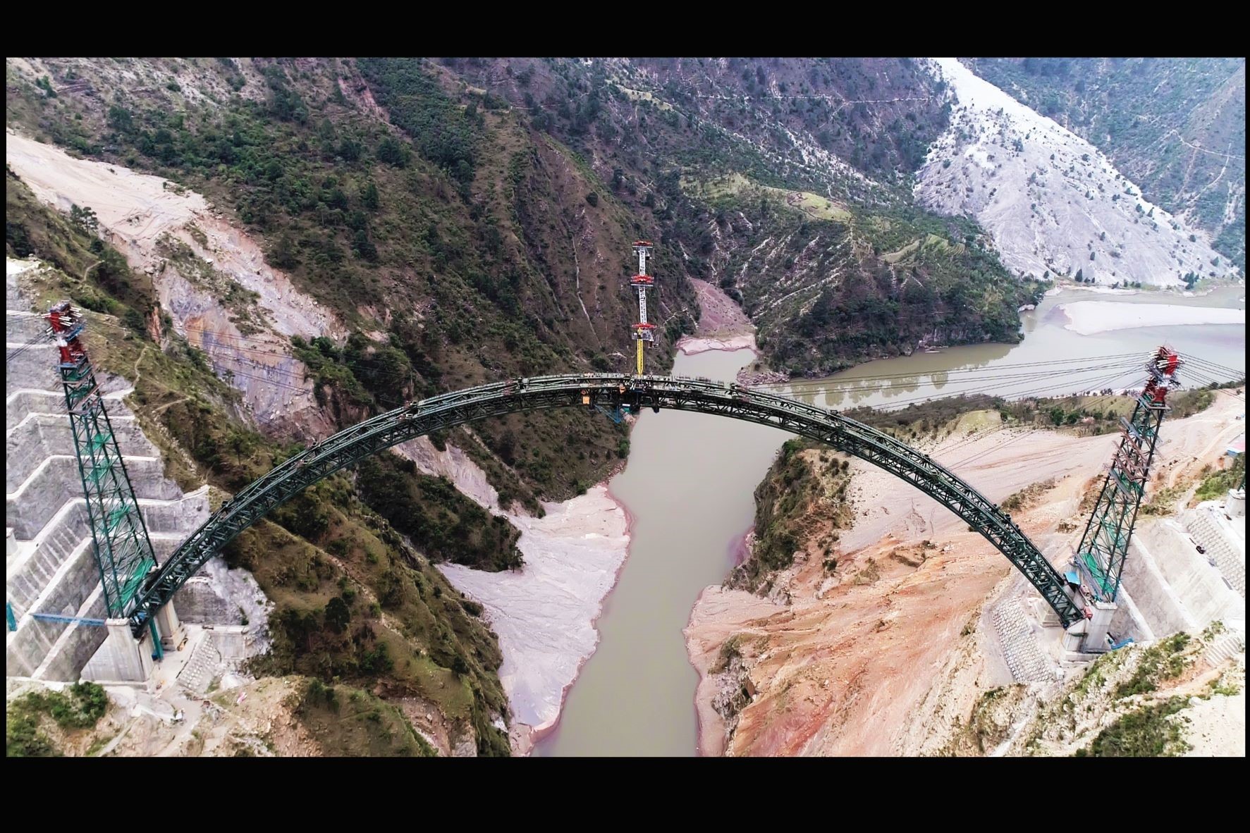 The two sides of the arch were connected in April 2021
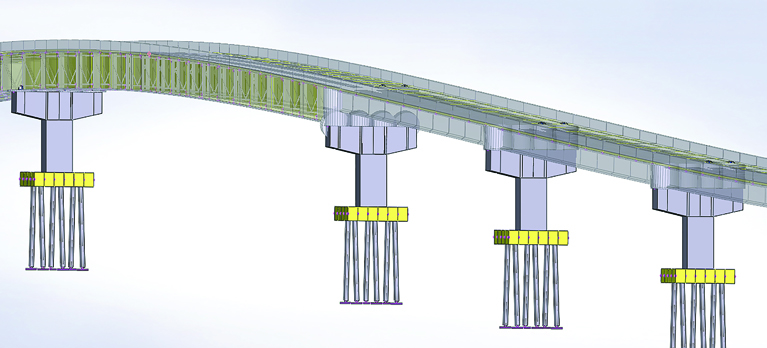
To counteract potential destabilising forces and moments in the ground around the foundations and improve shear resistance along the slip surface – the surface along which an earth bank is liable to fail under load – ground anchors were installed at the abutting foundations on both the sides of the crossing. Geotechnical analysis revealed that south of the river at abutting foundation S-40 there were very good ground conditions. Consequently, it was deemed that the installation of the Dwyidag bar anchor system by main contractor AFCONS would be sufficient to secure the dolomite rock there.
However, on the northern side of the valley, at abutting foundation S-50, complete consolidation of the rock was required. Freyssinet was contracted to fabricate and install the cable anchors and rock bolts for this side of the bridge under the supervision of AECOM. Starting at an elevation of 670m, five rows of 23m-long 32mm-diameter rock bolts were installed, totalling 92 bolts at 3m spacing centre-to-centre in both directions. Above these layers of rock bolts, up to an elevation of roughly 705m, 237 40m-long prestressed cable anchors with 100Mt design capacity for slope stabilisation were installed in nine rows, with 2.5m between each anchor centre in both directions.
The cable anchors are doubly corrosion-protected and comprise eight steel cables 15.7mm in diameter. The portion of the cable anchors which transmits the force to the surrounding soil – the fixed length – measures 10m and is surrounded by two layers of HDPE corrugated ducts. These provide double corrosion protection when filled with grout. The 30m-long free-length section transfers the force from the fixed length through the anchor head to the wall and is surrounded by grease-filled sheathing and encased in an HDPE corrugated duct.
Preparing the holes for the cable anchors involved drilling to a depth of 40m and a diameter of 160-180mm, with a 200-300mm-deep borehole to guarantee complete grouting at the end of the fixed length. The entire hole was then checked and flushed with air to remove loose material.
A water permeability test was also conducted to ensure water loss of no more than 3 Lugeons. If excess water loss was found, the hole was grouted using neat cement. “Some of the anchor locations at the extreme edges of S-50 consumed more than 5,000 bags of cement grout. In these areas we spent a lot of time to achieve the right results from the water permeability tests,” says Boovaraghavan Venkadesan, vice president of operations at Freyssinet India. The hole was then filled with water before the prefabricated anchors were inserted with a grout pipe.
One challenge involved finding access for the drilling rig required to prepare the ground for the first three layers of cable anchors, “Because of the minimum working width of the ledge at these locations, we had to modify the machinery, which took more than three months. For around 20% of the holes, we weren’t able to drill with the regular machinery.” The modified rig had a mast length of 3m and a crawler base of 2m by 2.8m, compared to 5.5m and 2.8m by 5.5m, respectively, on the regular rig.
The first stage of the three-stage grouting process involved grouting the space between the two HDPE ducts along the fixed length. Second, grout was injected into the pipes fixed inside and outside the HDPE duct until it overflowed from the top of the hole. After that, a precast reinforced concrete pad measuring 1.5m by 1.5m by 0.6m was placed around the grouted anchor using a crane.
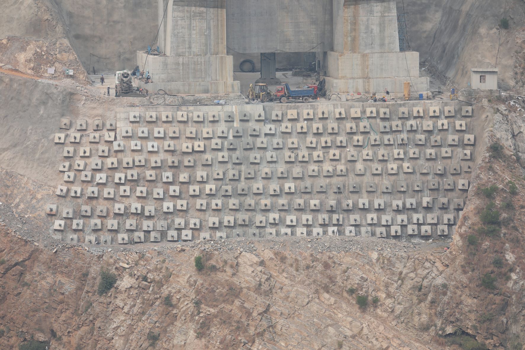 Some 237 cable anchors were installed at one of the abutting foundations (Freyssinet India)
Stressing of the cable anchors was conducted 14 days after the first two stages of grouting were completed to ensure the grout had obtained a strength of 30MPa. After this, a 350mm by 350mm by 50mm bearing plate and anchor block were installed on top of the concrete pad, and a 200t-capacity hydraulic jack was brought into position over the anchor head to carry out the stressing procedure. Some 150% of the working load was applied to the strands before being released to 110% of the working load, where the strands were locked.
The third and final stage of grouting was then undertaken, which involved filling the unfilled portion of the anchor inside the concrete pad. A galvanised steel cap was then mounted on the bearing plate using galvanised bolts and filled with a corrosion protection compound to assist in future restressing operations. Long-term monitoring of the anchors will ensure the safety of the slope along with timely restressing operations as required. The bridge is scheduled for completion in December this year.
Client: Konkan Railway Corporation
Contractor: AFCONS
Supply and execution of cable anchors: Freyssinet
Supply of bar anchors: DSI
Geotechnical Consultant: Indian Institute of Science Bangalore (AFCONS)
Geotechnical Proof Consultant: AECOM International (Konkan Railways Corporation)
Independent consultant: SCOTT Wilson (Konkan Railways Corporation)