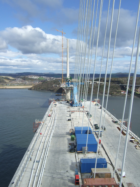
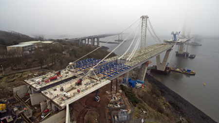
Just three years since Bd&e last reported from the new Queensferry Crossing near Edinburgh, the visible progress on Scotland’s new landmark is remarkable. During the last tour of the construction project in early 2013, the only activity that could be seen from land was three enormous sheet-pile caissons and a hive of crews beavering away on the north and south viaduct and earthworks construction (Bd&e issue no 70). Now it presents a breathtaking panorama with all three cable-stayed towers up to full height, cantilevered decks slowly closing the gaps between them, and the north and south viaducts jutting out to meet these dramatic structures. With the suspension spans of the Forth Road Bridge directly alongside, and the iconic elevation of the Forth Bridge World Heritage Site just beyond, the new bridge is rising to the challenge of being the new kid on the block.
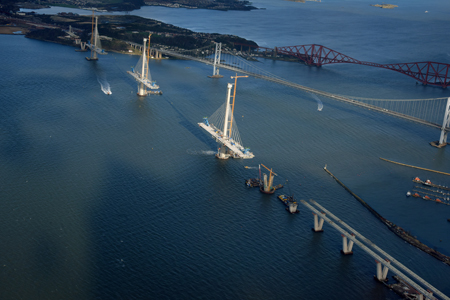
While the site has become a much-photographed visual feast for engineers and the general public alike, the amount of work going on is no less intense now than it was all those months ago – the difference being that most of the activity is now fully in the public gaze.
Forth Crossing Bridge Constructors project director Michael Martin is sanguine about the task ahead. As always in this part of the world, he acknowledges, the main obstacle that could prevent them from meeting the planned completion date – a date which no-one is willing to forecast at this stage – is the weather. And Martin has enough experience of working in Scotland, having already built several bridges north of the border, to know that its impact cannot be underestimated.
Critical-path activities have been weather-dependent for the majority of the project, although the contracting joint venture has made every effort to eliminate this as far as possible. Until the end of December last year, when the third and final one was topped out, construction of the 210m-tall single-shaft concrete towers was the main item on the critical path for the cable-stayed bridge. Although the jumpforms for the tower shaft were designed to be weather-resistant during preparation and concreting work, the process of jumping them was weather-sensitive and with three towers in progress at the same time, this had the potential to be a serious hurdle.
Other aspects of the tower construction were also at risk of being affected by poor weather – with materials and equipment being supplied to the work face by barge and tower crane, and operatives having to commute by boat over the Firth of Forth to their respective workplaces. “It can get a bit rough on the Forth at times,” remarks Martin dryly. Although concrete was pumped up the tower it still had to be delivered by barge from the site’s dedicated batching plant on the Rosyth shore.
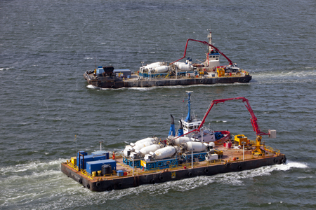
This batching plant, which according to FCBC has been working for three and half years without a significant breakdown, has a capacity of up to 240m3/h if required, and has achieved some impressive statistics so far. At the start of the year it had already produced a total of 170,000m3 at 99.8% compliance, and more than 107,000m3 of this had been delivered to the marine structures on the delivery barges — estimated at more than 1,500 trips. There have been large pours too — more than 20 were in excess of 1,000m3 and when the foundations were being constructed, the team achieved a world record for continuous underwater concrete pouring of 16,869m3 – a process that took 15 days to complete.
A large part of the visible works that have been carried out since Bd&e’s last visit involve concrete construction, but in the last eight months the erection of the steel deck units and cable stays has taken the place in the spotlight. The process of lifting the deck segments, which weigh on average 750t each and of which there are 122 in total, began in earnest in September 2015, although four ‘starter’ segments had been in place at each of the three towers since the previous year.
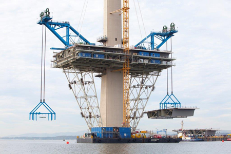
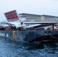
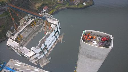
The starter segments were initially supported on huge trestles fixed to the lower part of the tower legs, and the process of erecting these trestles and the starter sections was a critical, weather-sensitive operation. At the central tower in particular, where the deck and tower are rigidly fixed by a so-called ‘power joint’, this was a complex and time-consuming procedure, Martin explains. “We had to first take the tower up through the deck level and cast in all the starter bars, couplers, PT ducts and so on. Once this was done we erected the trestles and temporary steel platforms which supported the starter segments so that the joint could be cast. They were sitting on the trestles for some months,” he recalls. The floating sheerleg crane Taklift 6 was used to erect the starter segments.
Transport Scotland project director David Climie recalls that this operation was blessed with good weather, a rare occurrence on the Firth of Forth. “The procedure in September and October 2014 involved ten lifts at each tower, to install the trestles, platforms and starter segments. We allowed 60 days plus 30 days of contingency for the operation,” Climie says. “In fact the weather was beautiful and we got everything completed in just 58 days!”
The starter segment box girder units were lifted without the concrete deck due to limitations on their weight; for the main deck segments the contractor’s preference is to lift them with as much in place as possible, to minimise the amount of finishing work required. Installation of wind-shielding is the main activity remaining once the deck is connected and the cables are tensioned.
Once the starter segments were in the correct alignment, with the first set of cables and the concrete deck in place, preparations began for the erection of the remainder of the deck. This is accomplished by the use of barges and lifting gantries, the latter working in pairs at each tower. The profile of the starter segments at the flanking towers also had to be adjusted to the right gradient for the finished structure — the free ends rising some 600mm off the trestles. This was accomplished by installing the first set of stay cables.
The final articulation of the bridge deck is such that the permanent movement at the north and south flanking towers will be longitudinal sliding, with the fixed point being at the ‘power joint’ at the central tower. During construction, however, there are temporary restraints in place at the flanking towers which will prevent movement until the full length of deck is complete. Expansion joints at the north and south abutments are being designed and manufactured by Mageba, and will be capable of accommodating a movement of some 1500mm in each direction, or 3m in total — some of the largest that the company has ever made.
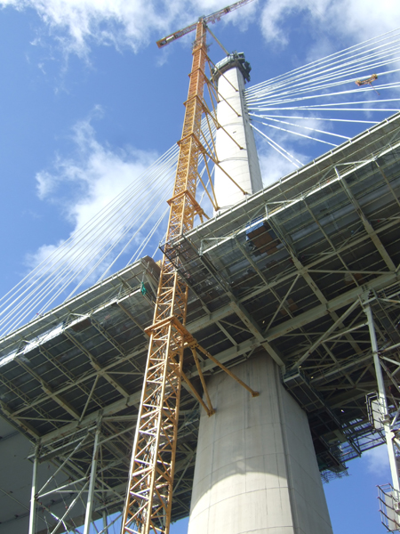
With the starter segments in their correct alignment, the erection gantries were then shifted forward to the front edge of the deck units ready for the lifting process to begin. At this stage in the project, explains Martin, the main shafts of the towers were still under construction. From the deck level up to the first cable anchors at approximately 150m elevation, the tower shaft was formed using an inner and outer shutter. As the tower cross-section tapers constantly from its base of 16m by 14m to the top of 7.5m by 5m, the shutters were designed to be adjusted as they rose. Once the level of the cable anchors was reached, the inner climbing form was removed and the cable anchor boxes were used as an inner shutter.
Cycle time for construction of each tower lift was variable, Martin says, and difficult to gauge due to the number of variables involved such as the crane availability, the weather, and the other operations that had to be carried out in tandem. Concrete for these units was a special mix which took a lot of development at the start of the project, he explains, since it not only has to endure being pumped three times over, but has to have sufficiently high slump to cope with the very congested conditions of the heavily reinforced tower cross-section.
After being batched in the plant, the concrete was first pumped to the quayside at the Rosyth where it was loaded into the concrete wagons on the contractor’s marine barges. These were then shipped to the appropriate tower base, and the concrete pumped out of the wagons and into the system that subsequently pumped it to the working face of the tower – more than 200m elevation for the very top units.
One event that had a massive impact on the project, and which could never have been foreseen, let alone planned for, was the sudden closure of the Forth Road Bridge in December last year (Bd&e issue no 82). With highway links between the main conurbation and the site offices and most of the construction compounds completely severed, the project team had to think on their feet.
“The first impact on the project was actually getting people to work,” says Martin. “The vast majority of our staff lived either on the south side of the Forth, or in Glasgow. Those in Glasgow would normally drive over the Clackmannanshire Bridge to work but with all traffic across the Forth having to use this route, it was massively impacted,” Martin recalls.
As well as getting staff to the site, the issue of materials delivery was a major problem with concreting of the south approach viaduct under way at the time. “We were using a special air-entrained concrete mix for this,” says Martin, “and it was not something that could be produced by a local supplier. The uncertainty of the transport to the site made it very difficult to plan effectively.”
Those staff able to work from home did so, and FCBC ran a shuttle bus service from the site offices to the nearby railway station for those who were able to travel by train. “We tried to get office space on the south side of the Forth but understandably it was in great demand,” Martin recalls. “Some of our staff got up at 3am in order to get in to the office some days.”
But there were at least some minor advantages to the closure, he admits, with the removal of traffic from the Forth Road Bridge north approach roads making it possible for some finishing works on the new interchanges to be carried out without the need to switch traffic around. Even this was limited, however, due to the fact that the asphalt supplier was on the south side of the Forth.
“When we were in a position to help out the team on the Forth Road Bridge, such as using our marine fleet to assist them, we did so,” Martin reveals. This included bringing in the equipment and materials that were required to carry out repairs to the suspension bridge, and making structural health monitoring experts who were working on the new bridge available to assist with analysis of the old one. Ultimately the closure was lifted after just a few weeks, ahead of the predicted schedule, and normal service was able to resume.
When Bd&e visited the site in early April, the main work that was under way was erection of the cable-stay deck segments. Only a handful were remaining to be installed on the north side span, and this was due to reach closure around the time of publication.
And with several dozen units already successfully erected, the site team can confidently claim to be well up the learning curve as far as deck construction is concerned. The Firth of Forth is tidal and this does have some impact on the erection procedure, but as work has continued and the team’s experience has grown, a more flexible approach is now being taken. Climie explains what impact this has had on the work rate. “In September we were only lifting at high tide, and in daylight,” he recalls. “Now we are lifting 24 hours a day, seven days a week, and have lifted two units in a single day on more than one occasion. The currents in the Forth are not as strong as I’ve experienced on similar sites, so it’s not so crucial that the operation to lift the deck off the barge takes place at high tide.” The only exception to this, he admits, is on the north side of the bridge where currents are locally stronger.
The main span steel deck units were manufactured in China by ZPMC and brought to the contractor’s Rosyth yard on ZPMC’s own ships in a series of deliveries. The 12 starter segments came on the first shipment, followed by two shipments of 36 units each, and the final 38 came in four smaller shipments, largely because of a shortage of storage space at the yard. There is room to store 78 units, but once they have their concrete decks added, capacity is reduced.
Sourcing steel from China may have raised eyebrows in some quarters but, as Climie points out, there is nowhere in the UK which has the capacity to produce such a huge quantity of deck units. “ZPMC also has its own fleet of ships,” he adds, “and this reduced the risk of delivery delays.”
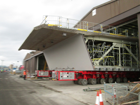
In the yard, FCBC uses self-propelled modular transporter units to wheel the steel box girders into the large warehouses where the concrete deck is cast and other preparations for erection are made. The concept is to do as much as possible in factory conditions, minimising the work that has to be done on the bridge itself and hence reducing the risk of delays from bad weather, as well as minimising the amount of working at height that is required.
The average weight of each unit is around 750t — only a third of this is steel, two thirds is concrete. In preparation for their installation, deck units are wheeled out onto one of two huge barges that are positioned by tugs. below one of six erection gantries that are in use on the project - two for each tower. Eadon Consulting assisted the main contractor with the design for these specialist gantries. The tolerance for positioning underneath the erection gantry at the working face of the cantilever is just 200mm, and the procedure of raising each unit the 55m to deck level generally takes a couple of hours. Once it has been adjusted to the appropriate geometry, a series of interlocking plates is used to make the initial connection.
The final deck connection, which is on the critical path, is a mixture of welding and bolting, and has to be carried out in a predetermined order to minimise weld shrinkage. The bolt holes are true-sized so there is no play on them and an exact fit is necessary. A concrete stitch is then poured to complete the connection, and the stay cables are installed. Martin explains that the concrete stitch is also on the critical path: “There was a lot of detailed preparation before construction began, to determine how much stress could be put into the stays at each stage,” he says. As the deck cantilevers get longer, they become more sensitive to external loads. The jump forms at the top of the towers have not been removed as they are not on the critical path and crane capacity is required for other operations such as cable installation. But once the cantilevers reach a certain length, the wind loading on the jump forms will impact cantilever stability.
With the deck connected, cables can be installed and this generally follows standard practice. Cables are formed of up to 109 strands, and they are positioned in a two-plane, fan arrangement along the centreline of the box girder deck. A total of 288 cables will be installed, including ten pairs of ‘crossover’ cables which are required at the mid-span of each of the two main cable-stayed spans to improve stiffness of the deck and limit deflections. Ten pairs from each tower overlap across a deck length of approximately 145m. “Installation of the crossover cables, the longest of which measure approximately 450m, will be one of the last operations to be carried out,” explains Martin; it will be done at the same time as setting the final profile of the bridge.
“We are not anticipating any problems with this part of the work, but we are aware that it’s a unique operation,” he continues. Again the deck erection and cable installation is a weather-sensitive process – the site team is aiming for a seven-day turnaround per deck unit, but as FCBC cable-stayed bridge engineer James Carr explains, many of the operations are dependent on the wind speed. The deck units can only be lifted off the barge if the wind speed is 11m/s; for raising to their final elevation, a slightly higher maximum of 14m/s is allowable, Carr says. The stay pipes are lifted to the tower anchors with two strands inside them, and this activity is wind-sensitive to the same extent as the lifting of deck units as it relies on operatives in baskets hanging on the side of the tower to thread the strand into the tower anchors. Once a set number of strands have been threaded and stressed in the pair of cables, which are installed simultaneously, the lifting tackle can be released.
As Bd&e went to press, 65 deck units had already been lifted into place and a further 45 were left to erect, with 34 still to receive concrete decks.
While public attention is mostly focussed on the main towers at this stage, the two approach viaducts are also significant structures that have posed their own challenges for the contractor. For these parts of the crossing, steel fabrication was carried out by Cleveland Bridge in Darlington, and both the north and south viaducts have been built by launching from the abutments.
On the south side, the 543m-long, six-span south approach viaduct is on a straight alignment and the twin viaducts could be built in 100m-long sections behind the abutments and launched forwards incrementally. Cleveland Bridge did all the assembly work on site as well as the factory fabrication. As the launch was under way, the v-shaped piers were being built ahead of the deck; two of them on land, one on the margin of land and water, and the others in cofferdams in the firth. Once all the steel had been launched the deck was cast in situ in sections from south to north.
Construction of the northern approach viaduct was a much more complex procedure, with a 222m-long section of deck being assembled on the shore and then manoeuvred forward by 230m and pivoted over a specially-built ramp into the correct alignment during a month-long launching operation in February.
The viaduct is a combination of the relatively-short viaduct which is just 76m of twin box girders, and a 146m length of full-width main deck, which consisted of 12 deck segments which had to be delivered as ‘flatpack’ and then welded and bolted together on the north shore. This part of the crossing is either over land, or too close to the shallow shore to allow deck units to be installed by the convential procedures used elsewhere. It took some nine months for the steel sections to be fully assembled with a 40m-length of reinforced concrete deck cast on the twin box girders at the north end to provide ballast during the launch.
During the launch, the leading edge of the deck had to be lifted up by 2m to bring it to the correct alignment to meet the deck units being erected at the north tower cantilever. This was achieved by pivoting the structure using the first of the two supporting piers as a fulcrum. Once the viaduct had been launched out beyond this pier, the trailing end travelled down temporary ramp walls at the north abutment. This, with the help of a king post and post-tensioning cables were used to raise the leading edge sufficiently to allow the structure to continue its journey over the second pier.
The ideal construction procedure, which would have seen the deck built at the final alignment and simply launched forwards, was not possible because of the presence of a large outcrop of rock behind the north abutment, which prevented the assembly area being excavated to an appropriate level.
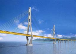
The Queensferry Crossing project will provide a replacement crossing of the Firth of Forth to the west of the Forth Road Bridge and it will carry general road traffic; it includes a cable-stayed bridge with a total length of approximately 2km and two 650m-long spans. Beside construction of the bridge, the project also includes connecting structures north and south of the Firth of Forth. In total, almost seven kilometers of road infrastructure will be built without disrupting traffic. Upon completion, the new bridge will ease traffic on the existing Forth Road Bridge. The principal contract to build the new bridge and connecting roads was awarded to the Forth Crossing Bridge Constructors consortium with a tender price of US$1.1 billion. Forth Crossing Bridge Constructors is a consortium of contractors Hochtief, Dragados, American Bridge International and Morrison Construction with a design joint venture of Ramboll, Leonhardt Andrä & Partners and Grontmij. The specimen design was carried out by the Jacobs Arup joint venture on behalf of Transport Scotland.