From single-span, rail-through-deck to sweeping multi-span trough-girder road bridges, weathering steel has come a long way from back-country forestry bridges, as seen in Tasmania’s Kanunnah Bridge over the Arthur River built in the 1970s for the Tasmania Forestry Commission. For all of these bridges, weathering steel was chosen due to its lower whole-of-life cost and low maintenance requirements, thanks to the formation of its protective rust patina. The latter significantly reduces the steel’s rate of corrosion over time when compared against an unpainted mild steel option, thus avoiding the need for the use of a protective coating and its maintenance in the future.
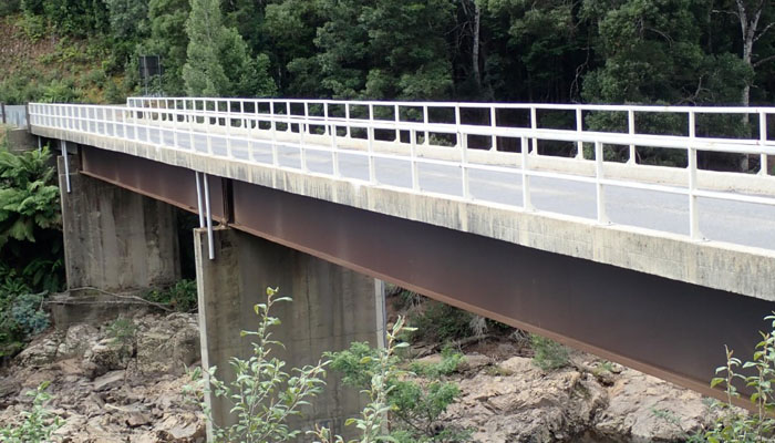
1970s-built Kanunnah Bridge in Tasmania
The increase in the use of weathering steel in bridges in the two countries can be attributed to the publication by the NZ Heavy Engineering Research Association (HERA) of the New Zealand weathering steel guide for bridges, first published in 2005 and revised in 2020, as well as HERA’s Weathering steel design guide for bridges in Australia, which was commissioned by Bluescope and published in 2017.
New Zealand’s first highway weathering steel bridge on Waka Kotahi’s New Zealand Transport Agency road network was built in 2005 and consisted of a 130t, 87m-long three-span structure. For the first seven years of its life, State Highway 1 Mercer to Longswamp offramp was the only such example permitted on the state highway network while its performance was monitored. Over subsequent years it was inspected by the author and lessons learnt incorporated into later bridges to maximise the benefits of using weathering steel.
One such learning was the identification of the correct patina colour to ascertain when it had fully formed, starting with a typical rusty yellow orange after the initial stage of exposure, becoming light brown and, finally, chocolate to purple-brown.
Six-month patina on Papakura Railway Bridge, New Zealand, and (below) fully formed patina on Mercer to Longswamp Off-Ramp, also in New Zealand
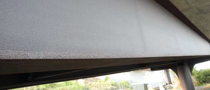
The timing of the colour and texture changes was found to vary with atmospheric conditions and the degree of direct exposure to rain. A rural, unpolluted atmosphere or sheltered interior beams results in a lighter colour and dusty texture, taking significantly longer to fully form its final colour, potentially up to 16 years or longer.
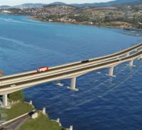
Fast-forward 18 years and New Zealand’s latest weathering steel bridge – currently under construction – consists of a 1,500t, 305m-long structure over seven spans.
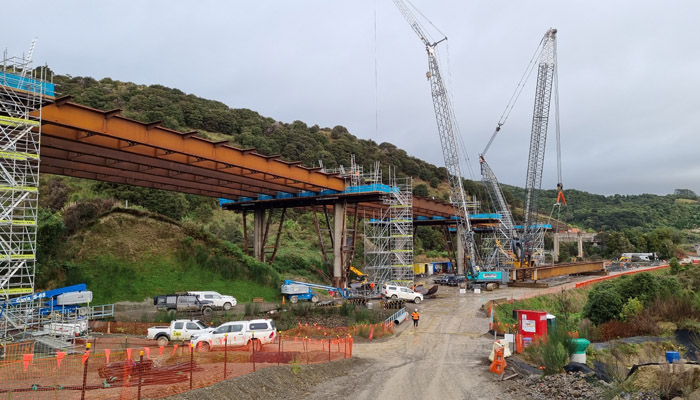
Eco Bridge Number 3
Designed by WSP, Bridge No 3 Eco Bridge on State Highway 3 Manawatu Tararua Highway is located over an ecologically sensitive area. Steel was initially chosen for its high strength-to-weight ratio, allowing for longer spans and a reduction in the number of piers. The weathering steel was selected to reduce the need for future maintenance, thus “minimising adverse effects on nationally critical vegetation and ecological habitats”, as stated in the project’s Design and Construction Report.
Over in Australia and designed by Arcadis, Transport for New South Wales’ first weathering steel bridges were recently completed on the Berry to Bomaderry stretch upgrade of the Princes Highway on the NSW South Coast. The Berry to Bomaderry composite bridges include majestic 800t trough girders made of Bluescope’s Redcor weathering steel. Again, the material was chosen due to steel’s strength-to-weight ratio allowing for longer spans compared to other construction materials, coupled with weathering steel’s low maintenance requirements. This resulted in not only a lower whole-of-life cost, but also negated the health and safety risks associated with refurbishing coatings over live lanes and at height, while mitigating the risk of traffic disruptions to the road users.
The Berry to Bomaderry composite bridges include 800-t trough girders and are Transport for New South Wales’ first weathering steel bridges
Also of note is the recently completed Bidgee Bidgee Bridge spanning the James Ruse Drive in Parramatta and built as part of the Parramatta Light Rail. Designed by Aurecon, the 1,425t, 64m-long single span structure is the longest weathering steel light-rail arch bridge in Australia and the second longest steel arch bridge in New South Wales after the Sydney Harbour Bridge. The new structure, which also accommodates pedestrians and cyclists, was again made with Bluescope’s Redcor weathering steel plate and thus continues the theme of a long-span, cost-effective and low-maintenance solution.
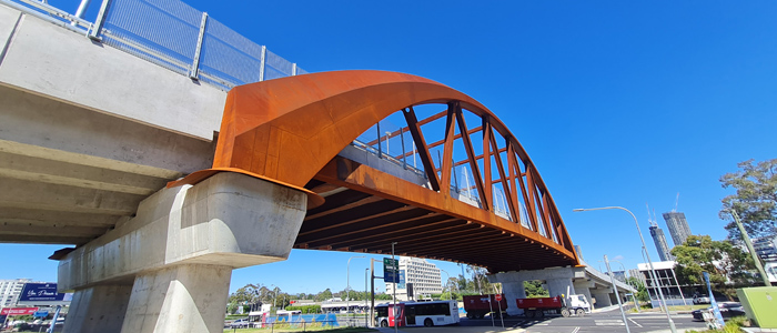
The recently completed Bidgee Bidgee Bridge in Parramatta is the second longest steel arch bridge in New South Wales after the Sydney Harbour Bridge
The use of weathering steel in Australia and New Zealand’s bridges is not confined to highway and pedestrian bridges. Prior to 2012, a large portion of Kiwirail bridges comprised a historic structural configuration known as a steel plate girder, some of which are on circa 100-year-old timber piles.
The introduction of weathering steel bridges in the form of State Highway 1 Mercer to Longswamp offramp in 2005 coincided with an internal review within Kiwirail to develop and implement standardised bridge solutions that offered economical whole-of-life performance and which could be applied to a variety of sites throughout New Zealand. Through this review process, weathering steel was selected as the material of choice.
This resulted in the replacement of four railway bridges in 2012 with a Kiwirail-developed variation of the popular North American ballasted through plate girder. The bridges, located on the North Island Main Trunk (NIMT) between Auckland and Hamilton, all had to meet four criteria. The ability for a quick replacement using the existing horizontal alignment, which typically requires no or little new embankment work; the inclusion of a ballast deck for ease of track maintenance and reduced maintenance costs; a shallow superstructure depth, as only minimal track raise was achievable and it was necessary to maximise available freeboard in flood conditions; and the use of Grade 350 MPa weathering steel, due to its strength and minimal long-term maintenance.
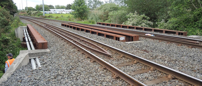
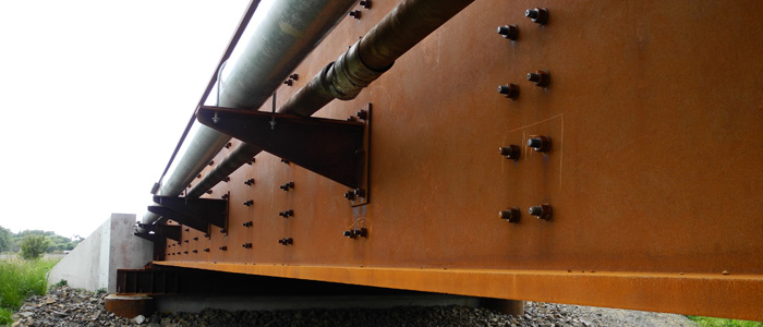
Bridge 312 is an example of a Kiwrail ballasted through-plate girder, featuring two single track spans each 14m long and weighing 30t
Since the construction of those four bridges, an additional eight weathering steel bridges have been built on the same NIMT line in the North Island of New Zealand and within 30km of the town of Taumarunui. All use the ballasted through-plate girder configuration, other than Bridge 207 NIMT, which has a more conventional weathering steel concrete composite deck configuration.
All 12 bridges were inspected by the author between 2017 and 2019, and were found to be in generally good order, given their recent age, with a uniform patina formation and the colour transition as expected for their respective age. A number of durability detailing observations were made on the more recently built bridges near the Taumarunui section of the NIMT and which were later used to improve the durability design of future weathering steel rail bridges.
These observations included signs of continuously wet surfaces on the bridges that featured a steel ballast tray detail with a bent steel plate bolted on to the top face of the ballast tray plate – which applied to all of the bridges except Bridge 207. On the affected structures, the ballast tray plate had signs of the edge of the tray base plate being continuously wet, which was attributed to condensation runoff collecting at the plate edge.
The damp surface risked impeding the formation of the protective patina, which needs to fully dry as part of the wetting and drying cycle. The level of wetness varied depending on the bridge location and the level of exposure to air movement of the bridge. Thus, to minimise this risk, a better detail would be to install the bent steel plate onto the bottom face of the ballast tray base. This allows for the water to run off without reaching the tray base, especially if a small ‘drainage lip’ is added to the end of the bent steel plate.
A drainage pipe located under the ballast tray deck was also found to be too short, as it stopped well above the level of the underside of the cross girder’s bottom flanges. It was recommended that it extend 100mm below the bottom flange, to minimise the risk of water droplets being blown onto the cross girders and increasing their time of wetness.
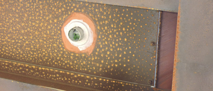
Example of a short drainage pipe that risks water being blown onto the cross-girders
An additional review of Kiwirail’s bridges has recently been completed. The aim was to identify additional savings to the North American-inspired ballasted through-plate girder-type bridges, as designed to the American Railway Engineering and Maintenance-of-Way (AREMA) guidelines and Kiwirail’s Design Brief W20111.
When compared against the European examples of through-deck girders, these AREMA designs appear to be bulkier and designed to more stringent design requirements than when compared against AS/NZS provisions. For example, the benefits of adopting the United Kingdom’s Network Rail design guidelines would include reducing the bridge width’s by up to 30% less to ‘platform clearance’, thus resulting in weight savings and in turn cost savings for new bridges. The proposal reduces the current 4.1m to 4.6m-wide ballast trays to 3.3- wide trays.
Review findings stated that a “reduced deck width also allows for refinement in the design of the structural members which means a bridge deck depth reduces to 250-300mm compared to the current depths of 550-600mm. Steel girder heights would roughly be 60% in height for a 20m span bridge. This would result in 14t reduction in ballast loading and 6-7t less steel in the girders.”
Finally, as part of this review, it was also proposed for Kiwirail to retire the use of AREMA guidelines, and design future bridges in accordance with AS/NZS 5100.6 (Bridge Design – Part 6: Steel and composite construction) and specify their fabrication to AS/NZS 5131 (Structural steelwork – fabrication and erection). Both changes are expected to result in additional cost savings, especially in relation to welding and fabrication costs, while continuing the use of weathering steel for all new steel bridges, where the environment is suitable.
Even though HERA’s Weathering steel design guide for bridges in Australia was only published in 2017, recent developments have led Bluescope to commission a revision of this document, with the aim of publishing it next year. This incorporates the latest guidance that is currently given in HERA’s New Zealand weathering steel guide for bridges that was recently updated in 2020.
Examples of such guidance, to be considered in the Australian guide, include adding Australian corrosion maps and using weathering steel in high humid environments, such as in Northern Queensland; undertake a review of current welding practices, including the procedure for multiple runs for thicker 10 to 12mm fillet welds; assess the efficacy of pulsed eddy current to measure the steel remaining thickness without removing the protective patina; and applying an alkaline poultice to dissolve graffiti and then steam clean.
There is another area where significant work is taking place. Concerted efforts are currently under way to address the challenges relating to climate change, with the aim to reduce greenhouse gases, especially in relation to common and high-carbon construction materials, namely structural steel and concrete.
It is a well-known fact that structural steel is one of the most carbon-intensive construction materials. At ‘up-front embodied carbon’ stage, each kilogram of alloyed steel has a global warming potential of 2.65 kgCO2 -eq, compared against softwood timber’s -764 kgCO2 -eq per m3 for sawn kiln dried softwood. This stage, also known as Module A, covers raw materials extraction, transportation, manufacture/fabrication and construction, known as the ‘cradle-to-gate’ cycle.
Work is under way at Module A to develop solutions related to the manufacture of structural steel, as seen with the development of fossil-free steel via the use of hydrogen and electricity to replace coal in the steel manufacturing process.
However, such innovations will likely require 10 to 20 years before they are fully embedded within the structural steel supply chain. As such, during this period, a series of solutions need to be identified and implemented within a short-, medium- and long-term basis that, when taken as a whole, provide a maximum possible reduction in carbon emissions.
A recently commissioned HERA report (Making steel the low carbon choice, 2022) considered such solutions based on achieving the target goals of 50% reduction by 2030 (short-term), net zero by 2050 (medium-term) and the long-term being taken as beyond 2050. There are some key learnings from this report.
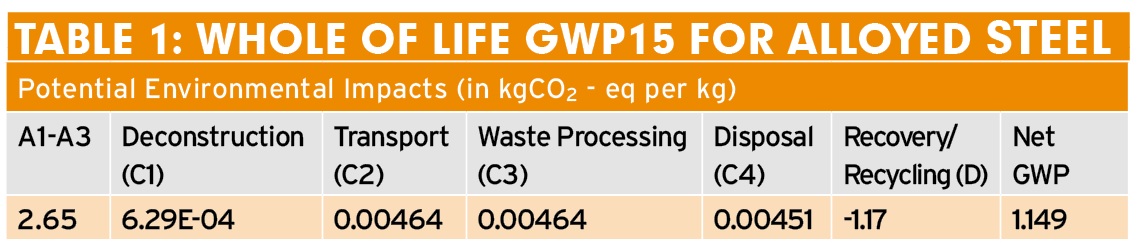
There is an apparent focus within the industry on Module A’s ‘product and construction stage’ due to an apparent limited understanding on how to allow for the remaining whole-of-life stages. Thus, as shown in Table 1 (above), the net GWP for alloyed steel can be taken as being 1.149 kgCO2 eq per kg.
Whilst it is appreciated that it is difficult to ascertain what occurs at the end of life of a timber structure, the current focus on the initial Module A stage appears to support an unbalanced outcome when undertaking lifecycle analysis, thus limiting the value of this process. This is further compounded by the current focus by the industry on carbon and global warming potential only, to the detriment of other crucial factors. Such factors include: accounting for more durable longer life structures; allowing for the financial cost when considering different options; and, more importantly, the abiotic depletion potential of raw materials - especially since the latter is already given in an environmental product declaration.
As such, the HERA report recommended the development of accepted industry best-practice guidelines, based on these factors and their effects on the lifecycle assessment. Steel sustainability credentials are currently focused on its infinite recyclability, and rightly so. Furthermore, until fossil fuel-free steel is commercially available, another solution should be considered in the form of steel reuse.
It was only recently, on 27 June 2022, that an EPD relating to the reusability of steel was published (EMR Reusable steel environmental product declaration). Here, for Module A, the GWP was listed as 0.0466 kgCO2-eq per kg due to the reuse of existing steelwork. In addition, Module D was listed as -1.708 kgCO2-eq per kg, mainly due to assuming that a large portion of the steel had been recycled, thus providing a net GWP of -1.6614 kgCO2-eq per kg.
This supports the case for the reuse of steel, either for existing structures or for consideration for the design of new modular and standardised steel structures. Coupled with the use of weathering steel, this increases the potential for both cost savings and reduced future carbon due to reduced maintenance activities, as listed under Module B.
The HERA Report also undertook a high-level lifecycle assessment, taking into account the different stages (Module A to D) of the process, for a pedestrian bridge and a single-lane road bridge, both based on readily available EPD data.
The pedestrian bridge is a two-span (31m, 31m) structure with a 100-year design life. The material options considered were; glulam (made from New Zealand radiata pine) - with the assumption to be replaced in year 50 and disposed at Module D; weathering steel bridge with a timber deck – the deck replaced in year 50, and the steel recycled at Module D; and a precast concrete bridge, with the concrete repurposed at Module D.
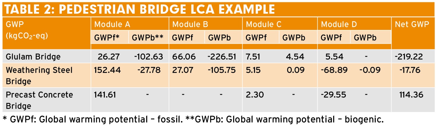
As can be seen in Table 2 above, the glulam bridge option provides the overall lowest net GWP, even though the bridge is replaced halfway through the 100-year design life. The second lowest option is the weathering steel bridge with the timber deck, which shows that even though it had the highest initial GWP at Module A, over the life of the structure the other modules assist in reducing the overall global warming intensity due to the negative GWP achieved through the use of timber (in both Module A and B) and the recycling of the steel at the end of life (Module D).
Finally, the concrete option has the highest net GWP, even though there is a small negative GWP due to the recycling of the reinforcement.
This comparison demonstrates the limitations of the current LCA process, due to the industry’s focus on the carbon and global warming potential only, as discussed above. In this case, considerations should have been made on the associated projects costs, especially since it is assumed that the timber bridge is replaced halfway through the 100-year design life. Therefore, while the timber options demonstrate the lowest whole of life GWP, it is likely to have the highest overall cost between the three options.
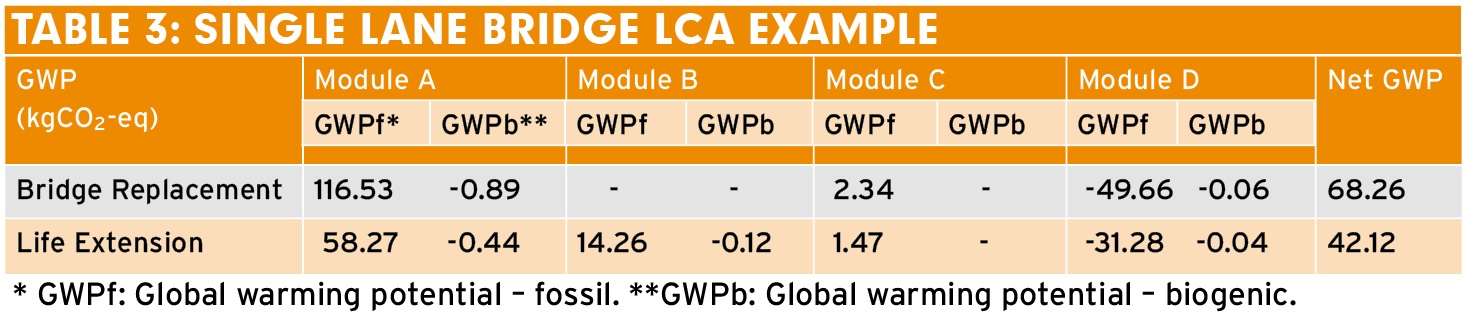
The single-lane road bridge example shown in Table 3 (above) consists of three simply supported spans of 12.2m. The considered options are for a new weathering steel bridge with a 100-year design life that is replaced by a new like-for-like bridge at the end of the design life, to achieve 200 years. At year 100, the replacement bridge GWP is added to Module A, as it is considered a new structure. The second is the same structure, undergoing life extension work over its life, to achieve a 200-year design life.
The results show the benefits of designing for a bridge structure beyond the current arbitrary 100-year design life. Aiming for a longer life structure, in this case 200 years, provides a lower overall net GWP, which coupled with the use of weathering steel, assists in minimising maintenance related GWP (ie Module B).
Again, the potential GWP reduction benefits of designing longer life bridges are currently not considered, due to the limited understanding on how to compare these scenarios. Especially for ageing bridges around the world, the need to replace them will introduce not only significant financial cost, but also increase potentially preventable GWP.
In conclusion, when compared against other parts of the world, weathering steel is a relative newcomer to bridges in Australasia. Over the past 20 years, it has proven its low maintenance credentials and its uptake has been accelerating, especially in Australia.
With the continual improvements relating to the design of more efficient bridges, with sustainability becoming a main driver, a well-designed and detailed weathering steel bridge in the right location has the potential of providing low maintenance solution in excess of 100 if not 200 years (or more).
Raed el Sarraf is technical principal – asset integrity management, at WSP in Christchurch, New Zealand