Flash-flood risk and a deep gorge have led to one of India’s first network-tied arch bridges being installed using a ropeway cable crane – a possible world-first in bridge construction.
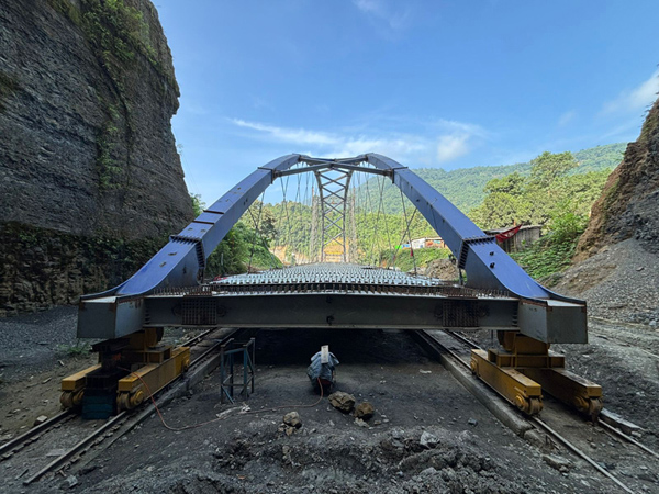
At the time of the design of the Tlawng River Bridge, no network-tied arch bridges had been constructed in India
Sited between Lengpui Airport and the Mizoram state capital city Aizawl, the new 103m-long Tlawng River Bridge is the new signature gateway for the city located some 25km to the south-east. The 14.25m-wide tied-arch bridge carries two lanes of traffic for National Highway 108 as well as two 1.5m-wide walkways on either side. Currently at its final stages of construction, the bridge spans a steep, 50m-deep gorge prone to flash flooding and is located within a Seismic Zone V region, the highest risk classification for earthquakes. The project is the latest – and hopefully last – attempt at building a crossing at a site that has proved disastrous for previous bridges.
The checkered history speaks for itself: a temporary Bailey-style bridge constructed in 2002 collapsed four years later. A second collapsed in 2014, followed by a third in 2016, which lead to an attempt to build a three-span simply supported crossing 60m in length. Construction of the permanent crossing had to be abandoned in 2018 due to scour effects on the foundations. Another Bailey-style bridge was then installed, the fourth of its type, which is still in place today. The new tied-arch bridge - attempt number six since 2002 – is being constructed for the Public Works Department of Mizoram by Poddar Infratech Bridge with detailed design by Force SE and design checking by Ramboll UK.
The concept design for the new bridge initially consisted of a through-arch bridge with locked-coil-strand vertical hangers. After securing the tender for the detailed design, however, engineering firm Force SE identified some issues with the suitability of the design for its location. The most significant was that the foundations for the half-through arch would be below the highest flood level, which would leave the structure at risk of suffering the same fate as its predecessors.
In addition, the foundations for the new bridge would be located on ground with the presence of shale. “We realized that this foundation was not feasible,” remembers Force SE partner and project lead Deepak Prajapati, “So we researched other options and we came across the network-tied arch. Although more challenging from an engineering point of view, we thought the result would be more advanced and more elegant.” It should be noted that, at the time of the tender, to the knowledge of Force SE no network-tied arch bridge had been previously constructed in India. “We pursued the network-tied arch because we found it really interesting as a concept.”
As the originally proposed concept design involved foundations in the scour zone, which would likely prove problematic in the future, the client was open to innovation. “And the alternative solution we proposed also fitted with their requirement of a bridge which is aesthetically pleasing and blends well with the environment. We convinced them that this would be an iconic bridge for the state and the city, and they were happy with it,” says Prajapati.
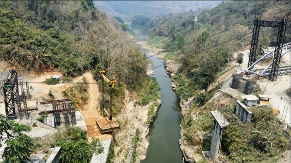
Four test loads were carried out before the launch, the last – and heaviest – test load weighing 220t
The new design features an arch with a 17m rise and a constant 80m radius formed by a hollow box section made from 10 bolted segments. The arch tie is a hollow box 750mm deep (at the ends) and with I-section cross girders spaced 2.5m apart. The arch and tie are connected by 28 steel hanger rods 56mm and 68mm in diameter. To account for the Seismic Zone V risk, the bridge is fixed at one abutment while on the other it rests on spherical bearings with 80mm movement capacity.
Producing the detailed work for a bridge typology little known in the country was a challenge in itself, but further complexity revealed itself when thoughts turned towards construction methodology.
The site, as previously mentioned, comprises a 50m-deep gorge prone to flash flooding at least twice a year, which radically narrowed the options available. Floating the structure and then lifting it by crane was clearly unfeasible. So was building the bridge in situ, as the temporary shoring required for the year-long build would also be vulnerable to flash flooding. The possibility of erecting the arch steel framework on one side of the gorge and then launching it seemed to hold some potential, but it too was deemed risky due to the in-river temporary supports needed. “So we had to cancel this one as well. The only possible way that came to my mind was using a suspension system and hanging the steel structure from cables and taking it from one side to the other,” remembers Prajapati.
Said method, however, had not been used by the contractor before, nor could the team find any examples of bridge projects that had used a ropeway system of pulleys and a cable crane for installation. At the time, it was thought that it could be a first in terms of whole-bridge installation and also in terms of load weight. “So it became a question of using first principles and common sense - with zero experience,” he recalls. “And, because the contractor was more accustomed to working from experience rather than from an engineering concept, we had to take control of the entire scheme, including the launching operations.”
The cable crane arrangement that was developed consisted of a system of lifting beams, pulleys, winches and cables supported by two portal towers, one 30m high on the Aizawl side (launching side), and one 10m high on the Lengpui side (destination).
The height difference between the two towers was designed to assist and guide the structure to the other side of the gorge by keeping the lowest point of the main cable catenary close to the destination abutment, thus helping to guide the bridge to its bearings. “If the towers had been kept at the same height, the lowest point of this main cable would have been somewhere in the middle of the gorge, where the arch would stop, and then we would be trying to pull it against gravity,” explains Prajapati.
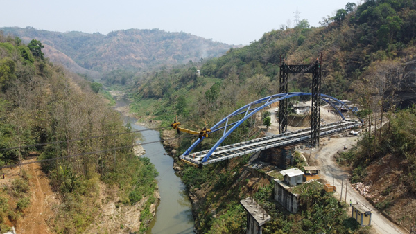
Multiple winches had to be operated simultaneously during the operation
A pinned foundation was used for both towers to avoid introducing a bending moment at the tower base: to counteract such a bending moment would have required a significant increase in the size of the towers. The towers were stabilised using 20 cables 24mm in diameter connected to anchor blocks behind them.
Atop the towers were placed saddles comprising steel guide blocks and PTFE sheets, which were used to direct the eight 60mm-diameter steel ropes that comprised the main cable support for the cable crane. The crane was connected by further cables to a steel beam under the leading edge of the structure. At its starting position, the cable crane was some 25m high above the bridge deck.
The safe transportation of the structure was controlled using a system of winches and winch cables, at times simultaneously. Winch 1, placed on the anchor block of the tower at launching side, connected to the cable crane via the saddle and served to restrain the crane as it moved down the main cable. Winch 2, located on the anchor block on the opposite side, the destination side, controlled cables that followed the path of the main cable to the cable crane and then vertically connected to the lifting beam under the deck. Winch 2’s role was to lift the bridge during its progress along the main cable so that its leading edge would align with the abutments. Winch 3, located at the destination abutments, controlled cables connected horizontally to the lifting beam under the deck. This winch served as back-up in case the structure failed to move in tandem with the cable crane. Winch 4, a replica of Winch 1 but on the opposite side of the gorge, had the role of pulling the cable crane up and towards the abutments when the structure was located at the lowest point of the main cable catenary, close to its final destination.
To account for potential seismic loads during the launch – as well as wind – some transverse restrainers were also necessary. Consequently, two winches were placed on either side of the bridge trajectory to restrain any transverse movement at the leading edge of the structure: side restraints were deemed unnecessary at the rear as the bridge here rested on rails: “But in the end there was not much wind and no seismic activity so we didn’t use them,” says Prajapati.
The complicated system was site-tested extensively over a four-week period in March this year. The four test phases involved first moving the unloaded cable crane between abutments, then adding a 50t load (sandbags), followed by a 100t load and, finally, a 220t test load. “We perfected the system and ironed out all the issues through the testing,” says Prajapati.
On the day of the launch, 7 April, the operation went flawlessly, with Prajapati personally controlling all four winches from a single console. “I had to constantly release Winch 1 [restraining winch] for the arch to move ahead, and also use winch 2 [lifting winch] to raise the bridge, which would naturally move down as it moved ahead and the height decrease. And Winch 4, the mirror restraining winch, all had to be continuously wound, as well as Winch 3. All four had to work together.” As it turned out, Winch 4 only had to be used for the final 2m of the bridge’s journey across the 100m-long gorge: “The behaviour of the system was pretty close to what was analysed. There will always be some plus minus. But it was decently close,” he comments.
Transportation of the 440t arch structure was completed in around six hours and was monitored using cameras located at 24 key areas, on the trolley, under the pulleys and the ropes. And the footage, which was captured using a wifi system, was also live streamed to the client’s offices in Aizawl.
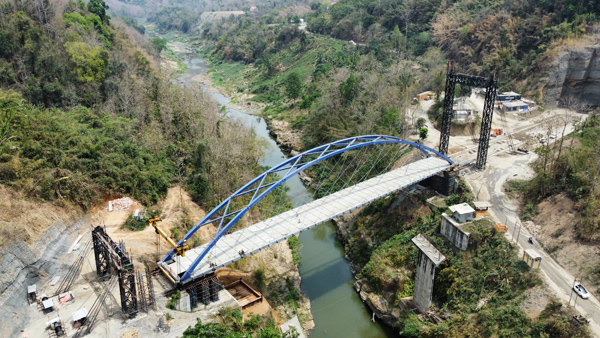
The Tlawng River Bridge after launching across the 50m-deep gorge
As expected, there were some learning points around the project, the most significant perhaps being the safety factor used for the ropeways. Although the literature recommended a safety factor of 5, Prajapati and his team worked to around 1.5, “If the factor had been 5, we would have been less anxious because it would have allowed for human errors.
“Errors could have occurred through the fact this method of launching system has never been used before and there were no direct literature references. There are uncertainties involved in the actual behaviour of system as everything was developed from scratch. And secondly, when things are carried out by third parties, there are risks with integrating different systems and make them work in harmony. So keeping a factor of five would have allowed us to sleep peacefully. But if you have a factor of 1.5, then yes, you are anxious, but then we did rigorous load testing of the launching system using dummy loads to be sure things worked out fine.”
The difficulty of working with ropes was also revealed during the test phase, “They are highly nonlinear elements so their behaviour changes,” remembers Prajapati, showing some frustration at how they tended to become stuck or entirely come off the pulleys, “So we had to take measures to avoid these things happening.” However, aside from applying the higher safety factor, Prajapati would use the same method again.
At the time of writing (June), deck pours on steel formwork were resuming following a two-week period of incessant rain which saw the river water level rise by around 20m due to flash floods: “And that is the reason why the construction by staging or transporting the completed bridge on staging was ruled out,” says Prajapati.
At the time of writing (June), the new Tlawng River Bridge was expected to be completed at the end of July 2025.
Bridge owner: Indian Ministry of Road, Transport and Highway
Client: Public Works Department of the State of Mizoram
Contractor: Poddar Infratech
Detailed design: Force SE
Checker: Ramboll UK