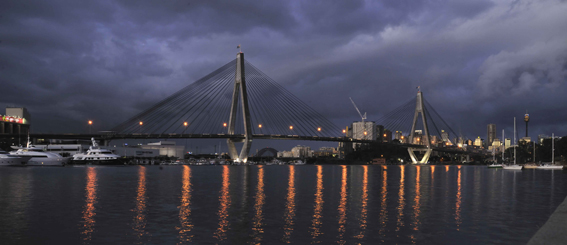
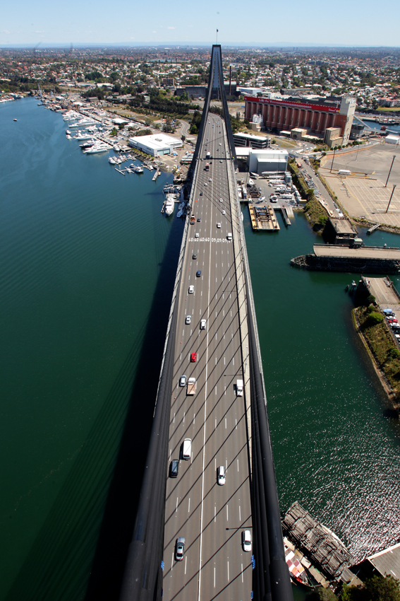
Increased traffic demands and changes to bridge technology are driving the upgrade of Sydney’s Anzac Bridge in a complex two-year programme of works to extend cable life, improve maintenance access and upgrade pedestrian safety. The cable-stayed bridge was built in the early 1990s and carries approximately 125,000 vehicles each day as well as providing a route for pedestrians and cyclists.
Since it was built, a number of things prompted the owner, Roads & Maritime Services of New South Wales to review the structural performance of the bridge and consider whether additional maintenance was required to extend the longevity of the bridge. Specific areas investigated included stay cable vibrations, water ingress and durability, stay capacity, access improvements and upgrades of the safety fence.
In order to deliver the rehabilitation project, Roads & Maritime Services formed an alliance with Freyssinet, Baulderstone, and Sage Automation, which was known as the Bridge Solution Alliance.They took a two-phase approach, with the first phase involving investigation of the existing structure and design development within a very tight six-month schedule. Phase two, which has a two-year programme, involves the implementation of the maintenance works designed in the first phase.
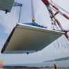
Through a collaborative approach between BSA and consultants such as Aurecon, Cardno and Leonhardt, Andrä & Partner, the first phase was delivered as planned. Phase two is now over halfway through; it began in August 2011 and is expected to be finished in September 2013. The bridge is a cable-stayed structure with two planes of cables connecting the towers to the deck via twin edge-beams that are 1.8m deep and range in width from 1.5m to 1.35m. The edge beams are heavily reinforced and incorporate prestressing; the reinforced concrete deck is supported by cross-girders which are spaced at 5.1m centres.
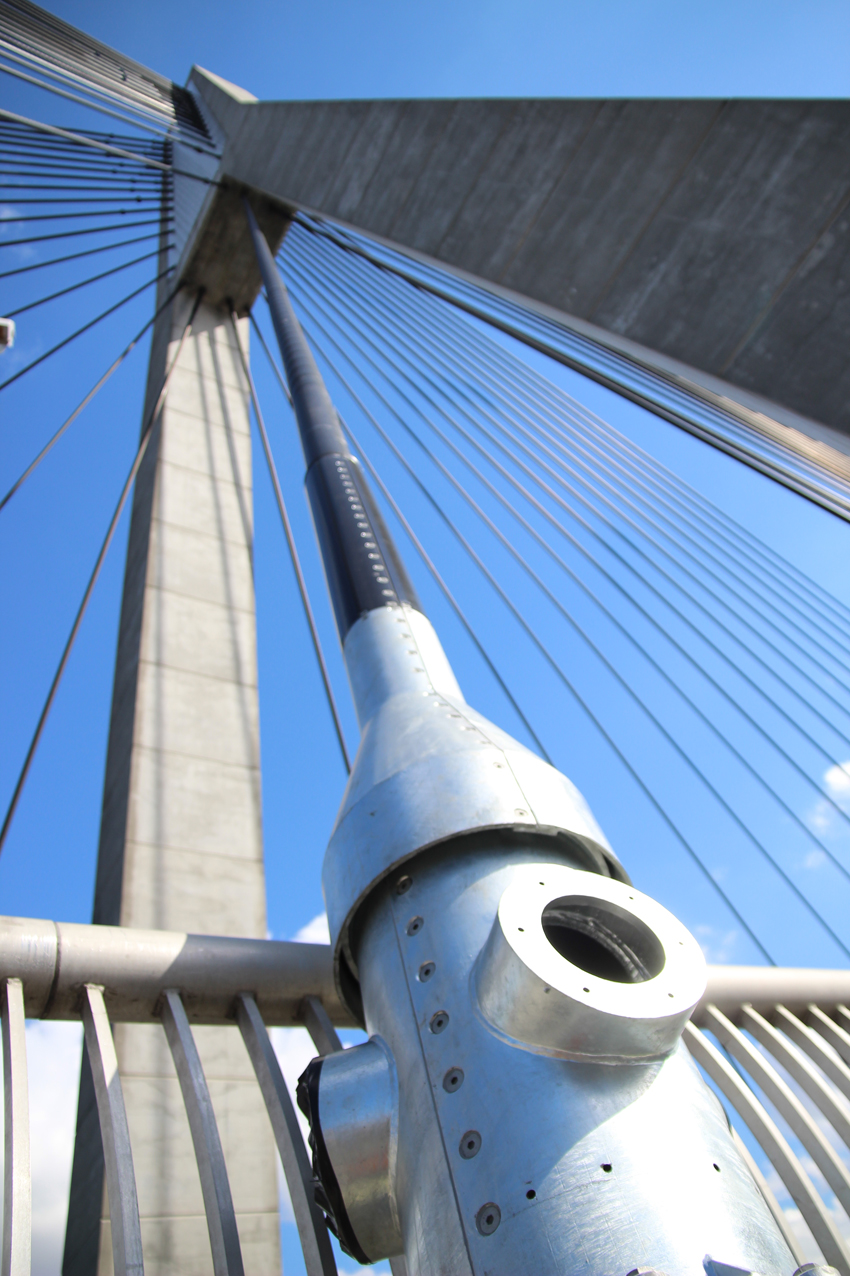
The bridge has three main cable-stayed spans making up a total length of 805m including approaches, with a typical deck width of 32.2m. The main span is 345m long and has 140m-long back spans which are supported by 128 stay cables that fan out from the top of two 120m-high towers. The stay cables consist of parallel strand wire; they range from 25 to 74 strands and up to a maximum length of 195m. The deck was originally designed to accommodate six lanes of traffic as well as a pedestrian/cyclist pathway but had sufficient capacity for an increased traffic load and is currently operating with eight marked traffic lanes.
Towards the end of the original construction, the stay cables were observed to be suffering rain-wind induced vibrations, as the phenomena is now known, and there was a concern that these large vibrations could cause a premature loss of fatigue life in the strands over time. On modern bridges, two design features are generally proposed to solve this problem; the first is to fix a helical rib to the exterior surface of the stay cable sheath. The second solution is to apply dampers to the cables at the bottom anchorages.
Before the alliance was formed, RMS worked with Freyssinet to specify a damping system for the Anzac Bridge, comprising of internal radial dampers for the longer stays and internal hydraulic dampers for the medium and short stays. However during the detailed design phase the team decided that for aesthetic consistency and to standardise the maintenance of the dampers, only internal radial dampers would be used. The critical issue with the helical rib was how to apply it to the existing cables.
The solution developed on the Anzac Bridge was to weld an in situ 3mm-wide rib to the existing sheath of each stay using a purpose-built robotic welder module fitted to a cable climbing robot. This part of the work was developed by Alpin Technik & Ingenieurservice jointly with Freyssinet. Because this type of retrofit has never previously been carried out at this scale on a cable-stayed structure, extensive trials were undertaken including a full-scale site test with a prototype welding unit. Improvements were made after this trial and a more robust site-specific unit was delivered by Alpin to weld the remaining 127 stays in a continuous welding programme.
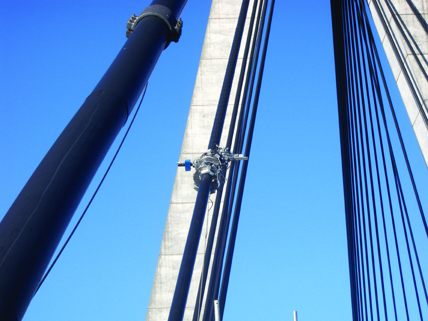
The robotic welder offers two main benefits - the first being safety, eliminating the need for people to work at height over traffic. Both the control of the welding and the inspection of the work in progress are performed by system operators working at ground level. Alpin’s cable robot is equipped with on-board cameras allowing the sheath and the application of the weld to be continuously inspected whilst the welding is being carried out. This allows potential defects to be quickly detected and fixed with minimal disruption.
The second benefit is cost; this method of in situ welding saves the cost of removing and replacing the sheaths, along with all of the associated costs related to erecting scaffolding and working at height. As Bd&e went to press, this work was almost complete. Internal radial dampers are also being installed to minimise vibration effects on the stays. These dampers will be installed at a height of 1.5m above deck level.
A two-part steel guide tube will connect to the existing steel formwork tube to provide support to the dampers and transmit the lateral loads from the internal radial damper back to deck level. The radial dampers and other stay components will be installed in two halves, requiring intricate two-part connections in order to connect these elements together and also to the original formwork tube protruding from the deck edge beam.
A fixed point is required behind the anchorage on cable-stayed bridges to ensure that vibrations in the cable are not transferred to the locking wedges where damage can potentially occur. To gain the maximum effectiveness of the dampers, the lever arm between this fixed point and the damper needs to be maximised. On modern stay cables this fixed point is created by a deviation or filtering device which is fully integrated into the anchorages.
However for the Anzac Bridge, a two-part system was devised whereby the anchorage and deviation collar are separate, with the deviation collar being located in the formwork tube, generally towards the top of it. But in order to maximise the efficiency of the damper, the existing deviators will be removed and replaced by new generation deviators specifically designed by Freyssinet. These will be installed further down the formwork tubes than originally. This solution has a number of advantages; firstly, that the existing formwork tube has adequate stiffness to resist the design loads from the dampers.
Additionally, the fixed point for the stays at deck level will be moved, thus arresting any loss in fatigue life due to the bending action of the stays under vibration effects. The dampers can hence be positioned at a lower level to minimise the visual impact and allow easier access for long term maintenance. A final advantage is that the new deviator is profiled to eliminate fraying corners, and this will maximise the fatigue life of the stay cables.
The bridge was originally designed with a provision for the stay ca