Reaching this milestone is an important step for the team, which is working to a tight schedule to open the new bridge by March 2022 – a challenging target given that the design of the bridge only started in May 2017. This is 19 months earlier than the original opening date of October 2023, with the Turkish president announcing the new goal more than a year ago.
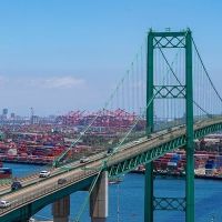
With a main span of 2,023m, completion of the suspension bridge will open a new category for the world’s longest span bridges, being the first in the world to have a main span of more than 2km. It is being built at the western end of the Sea of Marmara, some 200km from Istanbul, and, like the country’s three bridges crossing the Bosphorus Straits, will also straddle two continents, connecting the Asian and European parts of Turkey.
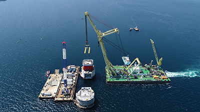
A floating crane was used to intall the lower blocks of the 1915 Çanakkale Bridge's 318m-high towers
Alongside the fast-paced programme, engineers must address the loading challenges that come with this world-record-breaking span. The main consortium responsible for building Turkey’s new 1915 Çanakkale Bridge consists of contractors Daelim, Limak, SK E&C and Yapi Merkezi, with consulting engineer Cowi responsible for detailed design. As well as a main span of 2,023m, the bridge has spans of 770m on each side, and approach bridges of 680m and 365m on the Asian and European sides respectively, making a total length of 4,608m. The two towers, which are being built in the water, will be 318m high, and the approach bridges include 15 additional piers, which are all based on land. The anchor blocks for the main cables are also land based and under construction.
The new bridge forms part of the central segment of a 324km-long motorway being built between Kinali-Savastepe. This will ultimately connect to the Gebze-Izmir highway and provide a circle of high-speed road links, improving highway routes around the Marmara Sea. More importantly, it will create another east-west route and help relieve pressure on the Bosphorus bridges, shorten transport routes, and encourage tourism development in new parts of the country. Finance for the 88.5km-long section, which includes the bridge and extends from Malkara to Çanakkale, amounts to roughly US$3.4 billion and is being provided by 25 banks and financial institutions from ten countries. The concessionaire’s contract period is 16 years, after which the motorway and bridge will be handed back to the Turkish government.
Design of the foundations has been governed by a number of main requirements – firstly to suit the ground conditions at the site, and in terms of loading, to withstand ship impact and seismic activity in what is a very busy shipping route in a region prone to earthquakes. All of this has to be achieved within the context of optimising the construction process.
An estimated 44,000 ships pass through the straits every year, including some of the biggest vessels in the world. Consequently, this level of traffic is also one of the drivers of the main span length. Potential ship impact levels are high, with static loading on the foundations set at 370MN for design purposes. In order to have a competent transfer of these loads from the sea level down into the ground, a significant amount of ground improvement has been necessary under the main towers to be able to transfer this horizontal load.
Extensive strengthening was carried out in the soil, not connecting directly to the foundations, but by including 2.5m-diameter steel piles in the ground. This design enables loads to be transferred down the shafts of the foundation into the base and then into the soil via these elements.
Steel shaft erection on the Asian side of the crossing
At the European tower, the ground conditions consist of approximately 36m of normal to slightly over-consolidated Holocene clay, below which the more competent Miocene mudstone extends to a great depth. It is locally intersected by relatively thin Miocene sandstone layers. The Asian tower is located above over-consolidated Pleistocene clay and sand deposits which are present in thicknesses of 6m and 4m respectively, and overlay the Miocene mudstone, which again is locally intersected by relatively thin Miocene sandstone layers.
The foundation design was also verified for the seismic loading – it is not possible to say if this or ship impact load is the governing criteria, as this depends on specific circumstances. But, the designers have worked to develop a design that meets all the requirements. The same mitigation measures designed for ship impact will also mitigate the potential seismic loading, which is a similar order of magnitude.
Three seismic events were considered in the design: the functional-evaluation earthquake with a 125-year return period; the safety-evaluation earthquake which had a 975-year return period; and the no-collapse earthquake which had a 2,475-year return period. Individual input for six locations in three directions was used, and seven sets of time series for the no-collapse earthquake.
The towers will be built on top of the two huge offshore foundation caissons, one on the European side and one on the Asian side. The European caisson is founded on 192 inclusion piles. These are 46m long and 2.5m in diameter and are driven into the soil to provide a vertical strengthening of the sea bed. Conditions at the Asian caisson are not as severe, and the tower here is founded on 165 inclusion piles which are up to 21m long. A similar design was used below the Osman Gazi Bridge over Izmit Bay in Turkey. This was also designed by Cowi and is in an area with very high seismic loads. The piles are open at each end and not only serve to strengthen the soil vertically, but also allow horizontal loads to be transferred into the ground without it failing. Although they reduce settlement of the towers and increase the lateral resistance, there is no direct connection between the piles and the tower. A 3m-thick gravel bed is placed on top of the inclusion piles to create a flat surface onto which the foundation caissons are lowered. The piles have a special ring structure and shear keys in the top to assist the load transfer from the gravel into the piles.
The rectangular footprint of the foundation caisson is the same at each tower, measuring a huge 83.3m by 74m at the base. Water depth varies from 37m at the European caisson to 45m at the Asian one. Each caisson is a hollow concrete structure consisting of 80 cells which were ballasted with water once in position. Each concrete caisson structure also incorporates two 18m-diameter shafts on which the steel tower legs will rest. These shafts begin as concrete structures at the base of the foundation caissons and become composite by the addition of inner and outer steel tubes over the upper length. Over the composite length, they have a total wall thickness of 1.2m, consisting of 16mm of inner steel ring, 1,159mm of concrete and 25mm of outer steel ring. These shafts are connected just above the water level by a tie beam.
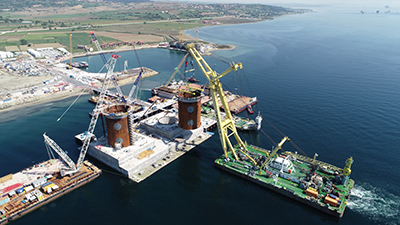
The contractors carried out two major operations to install the tower caisson in May this year
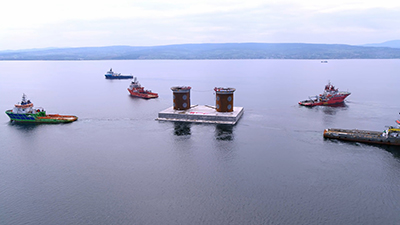
Both of the caissons are now in their final position, having been floated into position in May this year (see box, page 58). Fabrication of the caissons took place over 15 months on the site, starting in March 2018. Up to 1,300 workers and 9,000 truck-loads of concrete were used to build the caissons, each of which weighs an estimated 60,000t. The lower part of each structure was built in a huge dry dock, two of which were built adjacent to one another, and right next to the bridge site so that the caissons could be built concurrently, to speed up the work.
Once construction reached an expected draught of around 8-9m, the docks were flooded and the partly built caissons were floated out to wet docks in the open sea so construction could continue in deeper water. With the upper part of the foundation structure completed and the steel shafts in place, they were then ready to be taken out to the site and lowered into their permanent position. The total height of each foundation structure including plinth and tie-beam is approximately 10m higher than the water depth at the tower – 47m at the European tower and 55m at the Asian one.
The concrete tie beam which connects the foundation shafts will be cast in-situ: in the past, this was done in the traditional manner by fixing steel reinforcing and formwork on site directly onto the structure before pouring the concrete. However, with the short timescale and the need to work efficiently, Cowi’s engineers designed a new system which is anticipated to save around two months compared with the traditional method.
The in-situ element was divided into three parts for each tower – the two tower bases and the tie-beam. Formwork and rebar cages for each tower base were fabricated onshore then brought to site and installed directly. The lower sections of the tie-beams were cast onshore and the upper offshore, on the barge, before installation. This was considered a significant time saving against the tight schedule. The four prefabricated tower base elements have now been installed on site and the contractor is working towards the casting phase, which will make them integral with the lower structure.
Weak soil is present at both sides of the crossing, hence the designers decided to introduce side span tie-down to enable the anchor blocks to take advantage of the Miocene rock further away from the shoreline. Thus, tie-down piers were introduced at the end of each side span, where a series of high-strength tie-rods connect the cable to the base of the pier. Additionally, a longer side span was preferred to avoid side span piers being located at a geotechnical unfavourable slope and position prone to ship impact.
The anchor blocks, also made of concrete, are very large gravity structures with a footprint of 92m by 80m on the Asian side and 85.2m by 74.4m on the European side. They are drawn into the land side so that they can be founded on competent soils, and each is partly above ground and submerged according to the topography of each side. The anchor blocks themselves can be considered in two separate parts – the more massive part in the base, and the upper part, which effectively forms the cover for the splay chamber. The base of the second block has been completed and work is now focussing on the upper section with the splay chamber.
For the 318m-high bridge towers, steel was chosen over concrete to minimise construction time. For assembly purposes, the tower legs are broken down into 32 blocks, which are optimised in terms of weight. They will be lifted into position and bolted in the first instance, to enable fast construction, with welded joints completed subsequently. The five lower blocks up to a height of 60m are intended to be lifted into position by the floating crane, and the remaining blocks are designed so that they can be erected in smaller pieces by tower crane. To build concrete towers would take significantly longer. Ship impact forces also have to be considered at the base of the bridge towers, and the impact zone for this extends up to almost 30m in height. Over this area, local and semi-local impact are the governing criteria. This was addressed by increasing the skin plate thickness and by adding horizontal stiffeners to increase the local bending resistance of the skin plates.
In more general terms, the tower design was governed by the dead load of the world-record superstructure, as well as live loading from traffic, wind and so on. A lot of work has gone into identifying the traffic loading on the deck, to enable the designers to identify a more realistic, yet still safe, live load, particularly in the case of long loaded length where the load is not governed by single heavy vehicles but rather the average of many heavy vehicles. This allowed the designers to save weight on the superstructure and optimise the size of the main cable, which in turn reduces the dead load further. The deck is formed of twin box girders carrying three traffic lanes each and separated by a 9m gap to assist with aerodynamic stability. The total width across the two deck girders is 45m.
The bridge cable will be formed of prefabricated parallel wire system, erected strand by strand, and will be 869mm diameter over the main span and 881mm diameter on the side spans, with 144 and 148 strands respectively. The wire diameter is 5.75mm and each strand consists of 127 wires. From the anchor on the European side to the anchor on the Asian side, each main cable will be 4,384m long. The choice of cable type once again relates to construction speed, although this is also more commonly the cable type of choice for major suspension bridges these days. A dehumidification system will be installed and will be in operation when the bridge opens, and it will also have a full structural health monitoring system in place.