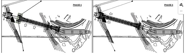
The new Drini Bridge is a bow-string crossing with a steel girder chord, a reinforced concrete slab, and a 271m-long span. It is characterised by a central arch section that bifurcates into four arch legs that extend down to the springers. Albania’s Ministry of Transport and Infrastructure commissioned the bridge to replace an earlier concrete structure and connect the region to Eastern Europe by carrying a new highway over Lake Fierza at Kukës, a city around 45km east of the border to Kosovo.
A major unforeseen challenge arose when the weathering steel structure, weighing about 5,000t and assembled behind the eastern abutment, was abandoned by a well-known Italian carpentry company that shall remain nameless. This left general contractor Impresa Salillari unable to complete the work due to insufficient assembly documents, which were either missing or not delivered. The situation was further burdened by the need to complete the works within 12 months to meet the inauguration date of June 2024.
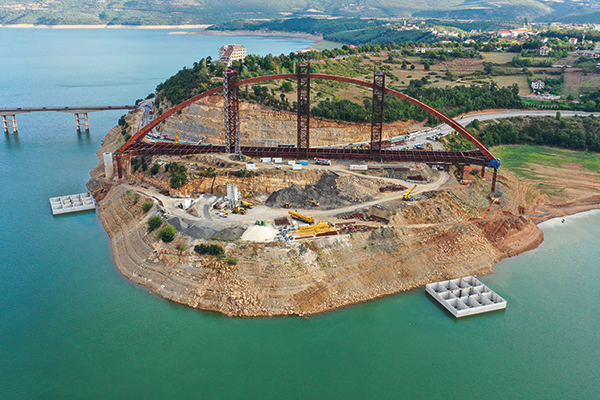
The Drini Bridge's construction site on Lake Fierza (Cimolai)
Cimolai was called in to intervene in two directions. Firstly, to immediately conduct a survey to check the state of the site, the installed equipment and the condition of the bridge. This included inspecting the deck and the hangers, which were relatively accessible, but also the interior of the large arch caissons and springers, which are critical points of the confluence of stresses, according to static schemes for operation and erection phases. There was no equipped pathway inside, necessary for future maintenance.
The second undertaking was the establishment of an in-house engineering task force divided into two: one group to validate the design, and another to design a staged erection process from scratch. This involved identifying and correcting any flaws, as well as conceiving, drafting, and presenting the erection project to the client and the independent third party. This was to be presented as a single block of work, complete in all its parts, with phases and detailed drawings of all equipment, along with global/detailed calculations.
To expedite instructions for workshops and site works, a maximum timeframe of two months was agreed for the second undertaking. By the end of this period, approximately ten calculation reports and 250 project drawings had been completed, averaging more than four project drawings per day.
Tracing the arch axis was a key issue for validating the design as it deviated up to 690mm from the node identified by the intersection of the chord’s horizontal axis and the vertical axis of the support apparatus. This likely stemmed from the previous firm’s construction design. The deviation, integrated into a finite element method global model, resulted in complete plasticisation due to traction over a 12m length on the upper platform of the chain at the confluence with the arch. To reinforce the section, butt-welded plates were added along the upper flange’s edges, reducing stresses without compromising aesthetics.
While assessing the weld quality, the Italian Institute of Welds (IIS) had discovered significant defects in type and extent within the four impost chambers of the arch. The chambers, which contained plates of considerable thickness intersecting with spatial geometries, required extensive reconstruction and follow-up inspections to satisfy European standards.
Regarding the erection phase of the project, reverse engineering had revealed some light concrete works that could be used for launching purposes, but also others whose function was obscure and therefore remained unused. In particular, there were temporary works present on both the construction and launching sides, as well as on the arrival side, that were considered suitable for supporting the runway beams. The runways were designed to assist transportation of the bridge towards the water during initial launching and towards the landing point, with heavy steelwork elements used for managing lateral loads. These temporary works, which consisted of shoring towers erected on piles, had been erected when the water level of the lake was low. The bridge itself was already assembled and set on temporary structures comprising main shoring towers and runway beams mounted on towers. A temporary arch was supported by vertical strand jacks in robust condition.
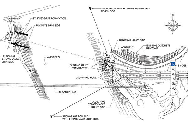
Layout of existing and supplementary structure (Cimolai)
Another notable feature was the presence of two moored vessels made of box concrete, each measuring 28m by 28m by 5m, which were designed to support half of the bridge weight during its crossing of the lake. The vessels underwent hydraulic, structural and water stability tests.
Once most of the welds had been repaired, 1,500t of specially designed steel equipment was constructed for the various land and mixed water-land launching phases. These operations involved a combination of translation and rotation techniques, which called for land and water teams to work in tandem at distances of up to 200m.
The deck was assembled on concrete blocks and temporary piers, and the arch raised from the deck in stages using six 70m-high temporary towers. Once the welds were checked, the central towers were unloaded, which transferred the load entirely to the side towers. The central tower was then removed, transferring the weight to the side towers and leaving the ends cantilevered.
![]()
Load transfer (Cimolai)
In this configuration, with the arch stretched and the deck temporarily compressed, the bridge was moved until the cantilever was positioned vertically over the water, where the two concrete vessels awaited. Equipped with pumps, temporary towers, and restraining elements for the bridge, the vessels supported approximately half of the bridge’s load, about 2,500t, using Archimedes’ thrust. Taking on this load required a change in the static scheme: from two cantilevers on the side towers, to support by the rear impost with four hydraulic pivoting slides, each with a capacity exceeding 2,500t. This adjustment facilitated the dismantling of both lateral towers for onward transportation of the structure.
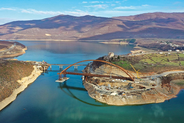 Strand Jacks pulling the Drini Bridge across Lake Fierza in Albania (Cimolai)
Rear strand jacks were used to pull horizontally until the end of the concrete runways was reached. In-water direction control was achieved through pivoting moorings, also operated by strand jacks anchored to powerful 200t bollards specially constructed on a piled foundation. Next, forward strand jacks (anchored on the landing side) took on the force from the rear to complete the barge journey. The rear-to-front change in the pulling point was required because of the physical constraints of the starting slope and the trajectory that the rear part of the bridge had to follow. The route followed along the existing concrete runways and involved intricate lateral translations and an in situ rotation of approximately 30°, executed on specially designed pivoting hydraulic slides.
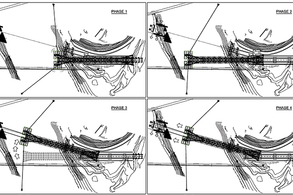
Phases of mixed land-water movement and change of pull (Cimolai)
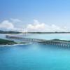
Once the opposite bank was reached, disembarkation occurred first from the right barge and then from the left, using elevated runways that extended over the water by 50m. Notably, the lake serves a hydroelectric power plant and is regulated by seasonal energy demand and upstream rainfall. Consequently, the runways featured a telescopic vertical post and a nose designed to accommodate a 10m variability in water level, or 275m-285m above sea level. However, the unfavourable combination of atypical rainfall – which exceeded historical averages – and low energy demand, resulted in the on-the-fly use of additional equipment to accommodate an unexpected altitude of 292m.
The final stage involved a spectacular operation: the vertical lowering of the entire structure by 10m to its final supports. This was accomplished with four hydraulic towers, each equipped with four rods, totalling 16 points of support. The deck was then completed with predalles slabs consisting of prefabricated reinforced concrete elements, onto which the slab was cast, the road surface finish applied, and street furnishings installed.
The Drini Bridge in its final position (Cimolai)
Cimolai’s work on the Drini Bridge concluded in May 2024, after which finishing works proceeded in preparation for its inauguration in June 2024.
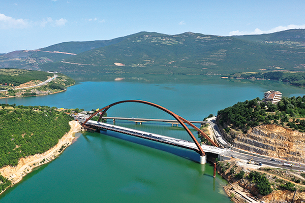
As a final point of note, the complexity of this entire project has served to reaffirm the value of Cimolai’s in-house protocol for evaluating the difficulty level of projects. The protocol assigns an erection class to a project based on Eurocode and a series of parameters. To prevent assembly from becoming a complex or improvised acrobatic engineering exercise, we believe that it is crucial that stakeholders compile and discuss such a document early in the operational design stage, well before any site activities.
Using this protocol, the assembly of Drini Bridge was categorised within the ERC3b class, the fifth and final achievable class through analysis out of six. The highest level, ERC4, signifies extraordinary works such as the transoceanic transport and assembly of the Panama Canal gates or the construction of large over-sea suspended bridges, such as the Messina Straits Bridge.
Such a protocol is entirely absent from the regulatory landscape, something that we believe needs to be addressed through a new Eurocode for land operations. Drawing upon DNVGL-ST-N001 – Marine operations, a comprehensive reference document of over 500 pages, would establish a solid framework for the industry. Without such guidance documents, whether for mega-structures or small bridges, cost analyses and assembly risk assessments can only be superficial.
Table detail of Cimolai’s protocol for evaluating project complexity
A detail of the protocol is included in this article (above) to encourage discussion on this important topic among the esteemed construction community.
Alessandro Catanzano is director at Cimolai
Client: Ministry of Transport and Infrastructure of Albania
General contractor: Impresa Salillari
Design verification, assembly and launching: Cimolai
Non-destructive testing: Istituto Italiano della Saldatura di Genova (Italian Institute of Welds of Genoa)