A new bridge with unsymmetrical arches and a curved deck has just opened in Guangxi in China. Futang Wei, Rijin Huang and Xiaoqun Gao report
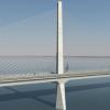
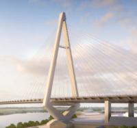
The dramatic Nanning Bridge over the Yongjiang River in Nanning City, capital of Guangxi, was the final masterpiece of bridge designer Tung-Yen Lin. The bridge, which was due to open as Bd&e went to press, has a 300m-long main span and is intended to look like a butterfly perched over the river. It will offer a new route from Wuxiang new town to the city centre, and links to Panlong new town on the south bank. It will also offer a connection to Beihai City and the Beipu Gulf Economic Zone.
The structure is claimed to be the first long-span curved girder steel arch bridge with unsymmetrical splayed ribs. It consists of two inclined steel ribs, a curved steel box girder deck, inclined hangers and cables anchored to the deck. The girder, which is curved in plan on a radius of curvature of 1,500m, shapes the main bridge. The obliquity of the eastern arch rib is 70o and that of the western arch is 66.5o. A combination of catenary, circular curves and straight lines is used to create the geometry of the complex axes of the two arch ribs.
This design of a bridge with unsymmetrical arches is claimed to be Lin's invention; it contrasts with the conventional arch rib design in that both arches lean outwards at different angles, to accommodate the curved girder. Horizontal connections between the arch ribs are unnecessary since the balance of the arch is maintained by its own rigidity and the inclined hangers. In plan, the two arches are oval-shaped, although in elevation they appear to be circular and in combination with the 300m-long curved deck girder they give the bridge something of a sculptural structure. The ribs form their own inclined planes, which connect below the main girder, supporting it and controlling the transmission of the three-dimensional balance.
The upper parts of the Nanning Bridge arches are formed of steel box segments, while the lower parts are concrete, the connection being made just above the level of the deck. The cross-section of the single cell steel box which makes up the arch rib is of constant width and height. Its curve follows a parabolic curve, varying from 5.6m at the midspan to 10m at the steel-concrete interface. In each arch plane, the arch axis of steel box arch rib segment is catenary, while the axis of the concrete section is composed of a circular curve and a straight line.
The main deck girder is formed of a single cell box girder, which is fully welded and is 35m wide, 3.5m deep at the centre, with the top plate of the steel box girder separated into lanes for vehicular traffic, cycle lane and footway.
Due to the unsymmetrical structure of the main bridge, four vertical tension-compression bearings are installed at the end of the box girder to constrain the vertical displacement and twist. Two plate bearings limit the transverse displacement of the box girder and two dampers with a maximum displacement of 160mm are placed longitudinally, so as to restrict the displacement of the box girder the bridge during an earthquake.
There are a total of 32 bundles of cable ties in the bridge, which are divided into four groups, eight bundles in each group. Each bundle consists of 24, 15.2mm-diameter strand and three backup holes. The cable is epoxy-coated unbonded strand cable which is 294m long. All the cable ties are installed in the box girder, anchored to the cross-beam of the arch rib platform and intended to balance the horizontal thrust of the arch rib and the transverse component of force in the main girder caused by the cable stays. Sixteen bundles are straight in the plane of the box girder, while the remaining 16 bundles are curved, to balance the transverse forces of the hangers. In elevation, all the cable ties form convex vertical curves with a 9,000m radius. Each cable is formed of OVM250-24 epoxy-coated strand cable system.
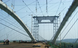
Construction of the superstructure of the Nanning Bridge began with the arch ribs, which were factory-fabricated and erected by use of a high-line system on site, before being stayed longitudinally and tied back to the temporary towers. Meanwhile, temporary horizontal braces were installed between the east and west arches. The combined action of the cable, the temporary horizontal braces and the hangers enabled the external component of force of the arch plane to be offset, stabilising the whole structure of the erection system. After the closure of main girder, permanent ties and hangers were installed in stages.
The high-line system had a main span of 452m, and it consisted of four main cables, supported by temporary towers which straddled the deck behind the arch at each end of the bridge. The tower crane and temporary tie-back towers were created as a single unit. The towers were built of steel pipe, formed steel and universal steel members. Because the arch rib leans outwards, a lateral traveller was set on the top of the tie-back tower to enable the main cables to move laterally to access each part of the splayed arches.
The four main cables on the high-line system each had a design load of 110t with two cables serving each edge of the structure. The steel arch ribs were each erected using two of the main cables.
Four smaller working cables with a design load of 5t each were installed, one on each side of the eastern and western main cable pairs, and were used for lifting small components, materials and equipment.
The steel arch ribs were each formed of 15 segments, which ranged in size from the shortest segment of 13.9m, to the longest of 21.2m. The lightest segment weighed 121.6t while the heaviest went up to 218t. Each segment had vertical lifting points, lateral connection points, stay cable anchors and three locating diaphragm plates.
The arches were erected from each side of the span, so during construction the cantilever was tied back to the temporary tower using an adjustable OVM250 stay cable system. A guide pipe and loading plate were put on each arch rib, while a longitudinal steel anchor beam on the temporary tower transferred the locking cable from midspan to side span. The locking cable was anchored to the ground 100m from the temporary tie-back tower. The force in the cable was adjustable at the tower in order to raise the cantilever to the right alignment. The most difficult part of the construction operation was the closure of the steel arches. Before closure, the temperature was measured every two hours throughout a 24-hour period; the target temperature was between 16oC and 22oC. The elevation and length variation of the erected segments were measured, to identify a period of the day when the fluctuation of these dimensions was at its lowest. As a result the closure operation took place between midnight and 4am.
The steel box girder segments were also factory-fabricated and delivered to site in 9m-long segments by barge. The erection process began at the midspan, then proceeded - with alternate segments - to each end. Because of the inclination of the arches, erection of each segment required the saddle of the cable system to be jacked transversely to an appropriate position above the rib. After each segment had been raised from the barge, its position was adjusted by use of the outer permanent cables and a temporary hanging cable. Because the erection of each segment involved loading the arch rib, the tie-back cable alone was not capable of supporting the thrust and camber force of the arch, so a temporary tied cable and flexible lateral brace had to be installed before erection.
During erectio