One of the main components of a major coastal highway planned to be built in Nigeria is a large-span bridge over the Bonny River. The 2.8km-long suspension bridge is intended to be part of a 600km-long highway between Lagos and Port Harcourt, which is being planned by the federal government of the Republic of Nigeria in association with local government agencies.
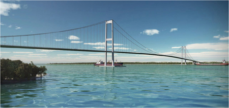
The project, named the East-West Coastal Road, includes three major river crossings, the largest being the estuarine crossing of the Bonny River some 35km south of Port Harcourt. Large oil and LNG tankers regularly use this river so a navigation width of 1.1km is required to meet international recommendations, and this demand led to the design of a bridge with a main span of 1.5km.
The total crossing is made up of a 2.8km-long suspension bridge with 1.5km of approach viaducts on each side. The Bonny River suspension bridge was designed by Hewson Consulting Engineers, working in association with Pearl Consultants, to give a deflected clearance to the deck soffit of 60m above high water level.
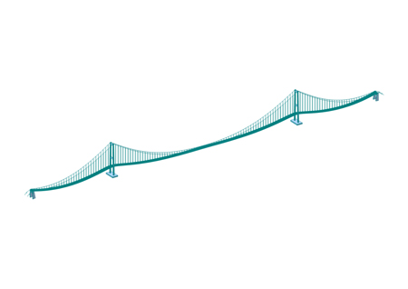
The bridge has H-shaped concrete towers rising to 230m above the water level, supporting the suspension cables, each of which have a diameter of approximately 950mm. The 35m-wide orthotropically-stiffened steel box girder deck is 4.8m deep in order to provide aerodynamic stability at critical wind speeds and is supported by vertical hangers at 20m centres. Global and local design of the bridge was carried out using a range of Midas software.
Global analysis of the bridge structure was undertaken using a 3D frame within the Midas Civil software package. A key benefit of Midas Civil is that it includes a suspension bridge analysis wizard that can determine the initial internal force conditions under permanent loads that are consistent with the reference geometry on completion of construction. As the design development continued, this facility was very useful for quickly re-establishing the forces in the structure under permanent loads after changes had been made to the design.
As with all long span bridges the assessment of second order effects due to tower slenderness was particularly important. The second-order analysis was undertaken using geometric non-linearity in accordance with the recommendations of the Eurocodes. A key part of this analysis for the concrete towers involved establishing moment-curvature relationships for key sections to ensure that the correct stiffness was adopted. Midas incorporates the facility to produce M-Φ relationships based on a wide range of non-linear material models for concrete and steel.
This quickly allowed Hewson to check that the tower stiffness was correctly represented for the maximum ultimate tower moments determined from the second order global analysis. The new highway crosses the delta region of Nigeria where the morphology of river systems is constantly changing and mangroves grow in abundance.
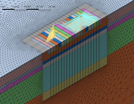
The concept of the Bonny River Bridge anchorage foundations was developed to cope with the unusual geotechnical conditions at the site, where thick layers of weak soft silty clays and sands overlie more competent dense sands and gravels. Given that the primary function of the suspension bridge anchorage foundations is to transmit horizontal forces of approximately 850MN from the suspension cables into the supporting ground, the weak upper strata presented a real challenge to the design team.
A solution was required to create a foundation capable of transmitting the huge horizontal forces into the stronger layers encountered at 20m depth whilst at the same time limiting long-term and transient movement of the anchorage. After a number of iterations the final design proposed the installation of four, 120m-long diaphragm walls to a depth of 30m, connected with an 8m-deep capping slab.
Below the capping slab the parallel, reinforced concrete, diaphragm walls create a structural arrangement that is stiff in the longitudinal direction and will carry the horizontal forces through the weak upper layers to a sufficient depth that the movements can be controlled and predicted. The total footprint of each anchorage foundation is 120m by 80m.
In addition to the horizontal forces, vertical forces of approximately 3,930MN, principally from the weight of the concrete anchor blocks and capping slab, are resisted by the diaphragm walls. They are supplemented by the addition of 2.5m diameter bored piles of approximately 55m in length. Analysis of this complex soil-structure interaction was carried out with Midas GTS, and using a solid 3D model of the foundation within the soil strata. Soils were modelled using appropriate non-linear models and the sensitivity of the input parameters was checked in relation to the effect that it had on anchorage movement and thus global stiffness.
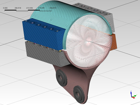
This enabled Hewson to predict movement of the anchorage in relation to the various construction stages and service load combinations with a reasonable degree of confidence. The movements were used to generate foundation stiffness values that could be input into the Midas Civil global bridge analysis model. The GTS modelling also produced forces and moments for the reinforced concrete design of the capping slab, diaphragm walls and piles. The suspension cables pass over the towers through steel cable saddles, each of which is anchored into the top of the tower. While the cables generate a vertical force of 450MN, they are also subjected to large transverse and longitudinal forces caused by wind, temperature and other live loads.
The saddle is thus a critical component in the transfer of the massive forces from the cables into the towers, and it is designed to be approximately 5.8m long by 4.4m wide and 3.1m high, fabricated using a plate-stiffened steel casting in high grade steel. For this element of the design Hewson used Midas Civil to create a plate model of the saddle that took into account the actual geometry and thickness of the various components. The vertical force was applied as a radial load along the base of the saddle groove.
Additionally, a horizontal pressure of 33% of the ULS vertical load was applied to both of the saddle trough walls to represent the flattening effect of the saddle. In addition to undertaking yield checks, the saddle stiffeners were checked for buckling, using linear Eigenvalue buckling analysis. Another key aspect of the design was the clamps, which connect the vertical hangers to the suspension cables.
These clamps work through friction by exerting a large confining pressure on the main cables using tensioned bolts. The hanger clamps have an internal diameter of 950mm and are required to support a maximum load of 15.5MN. The clamps which will be subjected to the greatest vertical loads are those closest to the tower, which receive approximately three times the load of the next nearest clamp, and those closest to the anchorage. It would not be feasible for all the clamps to be designed for the maximum load, thus it was decided that these would be designed independently and all others would be a standard design.
Given the complex geometry and the desire to produce an efficient design, Hewson chose to use Midas FEA to create 3D solid models of the clamps. One of the main challenges with the analysis
