Construction of a new cable-stayed bridge in Vietnam is set for completion in October this year. Iain Hubert reports on progress so far
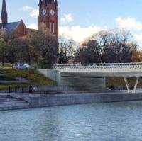
Almost two years on from the start of construction work, the landmark Phu My bridge can now be seen from many parts of Ho Chi Minh City. With one of the two main towers completed it is already possible to see how the new link will dominate the entrance to the Saigon River and become an integral part of the skyline of the city.
The bridge is being constructed by the Bilfinger Berger Baulderstone Hornibrook Consortium, a joint venture of two companies which form part of Bilfinger Berger, based in Germany.
The Phu My Bridge will link district 7 in the south west with district 2 in the north east of Ho Chi Minh City, crossing the Saigon River close to the point where it becomes the Dong Nai River. It will form part of a new ring road currently under construction around Ho Chi Minh City, becoming a vital part of the south eastern section of the ring road and an important transport link connecting the southern Mekong delta region to the central and northern parts of Vietnam. Goods traffic from the south will then be able to bypass the city centre to the east.
The client for this US$105 million project is a private consortium made up of both state and private companies. The Phu My Bridge Corporation holds a 30 year concession for the project; it will build and operate the bridge as part of a toll road scheme before transferring the bridge to public ownership.
Private finance raised by PMC is combined with export credit guarantees from Germany, France and Australia to fund the scheme. As part of the financing arrangements, almost half of the contract expenditure must be in these three countries. Three aspects of the finance arrangements - private sector infrastructure, private sector BOT scheme, and export credit finance - are firsts for Vietnam.
When construction work first began, the team anticipated that it would take some 34 months to complete the project, but optimisation of the construction methods and the use of specialist equipment has enabled some of this time to be saved. The contractor is currently targetting to open to traffic in September this year, a total construction period of just 30 months.
The scope of BBBH's contract includes the design and construction of the main bridge, a 705m-long cable-stayed crossing with a central span of 380m, as well as the approach viaduct structures on either side of the river. These extend to approximately 760m length on the district 7 side of the river, and 640m on district 2.
Design of the main bridge and approach structures was split into two packages, with the design of the cable-stayed structure being carried out by French consultant Arcadis. The approach viaducts were designed in Australia by Cardno; all the designs were coordinated by BBBH staff in Vietnam. Independent checking was carried out by Tony Gee & Partners.
Navigational passage for river traffic is provided with a minimum 45m vertical clearance, at high tide, over a 250m wide zone at the centre of the bridge.
The total width of the main span deck is 27m, this incorporates three lanes of traffic in each direction, two car and truck lanes, a separated motorcycle lane and footways for pedestrians.
Each of the two main bridge towers is supported on twenty eight bored piles each approximately 2.1m diameter and 80m length; meanwhile the towers themselves are H-shaped and are approximately 140m high. The main bridge deck is designed as an in situ, reinforced concrete slab supported on longitudinal and transverse beams and suspended from the towers by the stay cables. The deck is constructed in balanced cantilever fashion using formwork travellers to carry the deck elements while installation of the stay cables proceeds simultaneously with the casting of the deck.
To maintain control of the critical path, BBBH elected to construct all elements of the main bridge, including pilecaps, towers and deck, using direct labour. Stay cables are being installed by specialist Freyssinet, while a large part of the approach structures is subcontracted to Vietnamese contractor Chau Thoi Concrete Corporation 620. All subcontractors are closely supervised by BBBH staff.
Foundation works for the main bridge started in July 2007, however the team quickly decided that the locally-available equipment and resources which had been planned to be used for construction of the 2.1m diameter bored piles would not be able to meet the requirements of the programme. Instead, equipment and supervisory staff had to be resourced from offshore; however the three month delay that was initially caused by this decision was subsequently recovered by accelerating the subsequent piling works and tower construction.
Both of the main tower pile caps are located in the river so piling equipment worked from barges, with concrete delivery by pump from the adjacent riverbank. The pilecaps themselves are located above low water level so permanent formwork comprising precast concrete panels was used to form the soffit and sides. The soffit panels were supported on a combination of the permanent pile steel casings and some temporary piles in between the two permanent pile groups to allow casting of the bottom 800mm-thick strip of the pile cap. The precast side panels were then mounted on the completed 800mm thick strip and the remainder of the pile cap was cast inside them.
Each leg of the H-shaped bridge towers is a box section whose outer dimensions vary from 5.5m by 7m to 3m by 5m. Stay anchorages are located inside the box. Loop tendons in the tower head, ranging from four, seven-wire 15.7mm-diameter strand to 13 seven-wire 15.7mm-diameter strand, allow the box to resist the stay cable forces and 40mm and 50mm-diameter prestressing bars are used to counteract the bursting forces from the anchorages.
The pylons are being built using self-climbing jump forms which were designed specifically for the project to accommodate the change in section of the shaft (see box). Reinforcement for the towers was prefabricated, with two elements for each 4m lift. On the upper tower these elements were match-fabricated and incorporated the stressing and the stay cable anchorage tubes which were held in position by a temporary steel frame. This use of prefabrication, together with couplers forming the connections on the majority of vertical bars, ensured that a four-day pour cycle was achieved.
The legs of the towers are linked by two cross-beams; the lower of which was built on top of the pile cap. The steel falsework and formwork required for the first three deck segments was then erected on the cross-beam and the combined 1200t unit was raised 40m to its final position using strand jacks located on a temporary strut between the tower legs. When it reached its permanent location the cross beam was stitched and stressed to the tower legs. This method minimised the amount of work to be carried out at height and resulted in a programme saving as the completed pier table was available for deck construction earlier.
Balanced cantilever construction is used for the bridge deck, with 10m-long segments poured in situ using a form traveller. Each segment consists of two, 2m by 1.5m longitudinal beams, two 2m by 400mm transverse cross girders, two 1.5m by 2m by 3.2m anchor pods in which the stay cable tubes are located, and the 250mm-thick deck slab. The deck is prestressed transversely at each of the cross-girders and longitudinally over the central 170m of the span. As with the tower, maximum use is made of prefabrication in its construction. The anchor pods and transverse beams are precast and the reinforcement cage for the longitudinal beams is pr