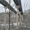
Forty kilometres north of New York City, the Tappan Zee Bridge, which spans the Hudson River, has reached its expiry date. Built in 1955, the steel cantilever bridge was designed for a service life of only 50 years and far fewer vehicles than it currently transports on a daily basis. But the New NY Bridge – the capstone in the initiative to rebuild America’s infrastructure – is quickly rising to replace it. At a cost of more than US$3 billion it is the largest construction project in the history of New York State.
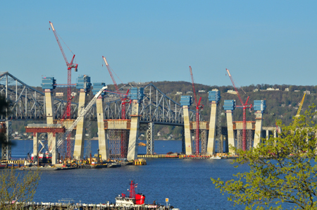
Photo: Andre Markarian
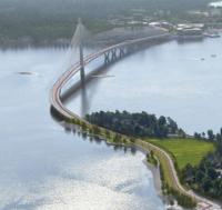
The New York State Thruway Authority awarded the design-build contract to replace the bridge to Tappan Zee Constructors, a consortium of Fluor Enterprises, American Bridge Company, Granite Construction Northeast and Traylor Bros and designers HDR and Buckland & Taylor. The new bridge is comprised of two, 4.8km-long parallel bridges with cable-stayed main spans. Each of the bridges will have a 679m-long, three-span channel unit with a 366m main span and 4.8km of concrete piers and steel girder approach spans carrying eight traffic lanes, four emergency lanes and a bike path and pedestrian walkway. The new bridge has also been designed to accommodate a future addition of rapid transit or light rail.
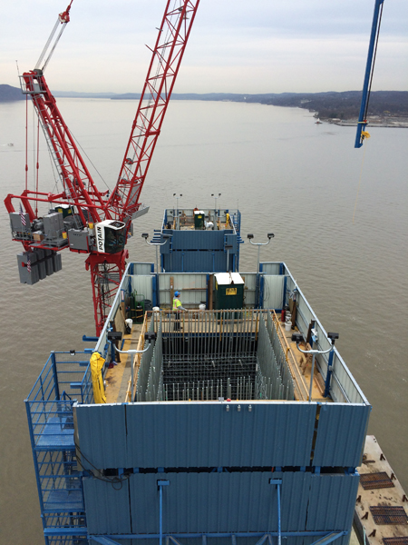
The focal point of the cable-stayed main span is the four towers; a total of eight splayed legs, the pairs connected by a cross-beam below the road deck. In order to meet the aggressive construction schedule, all eight 125m-tall concrete legs are being built simultaneously. To accomplish this daunting task TZC built three floating batch plants and eight independent jump-form systems, one for each tower leg.
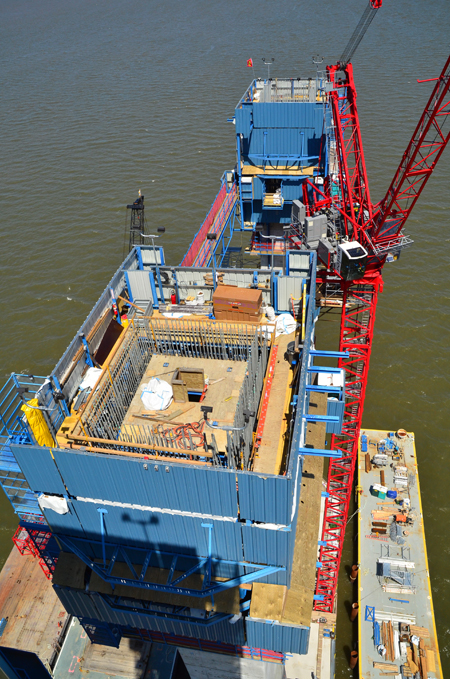
Photo: Andre Markarian
Each leg is being built in 26 separate lifts of heights that vary between 5.5m and 2.7m. TZC enlisted the services of specialist OM Engineering to design and supply almost 635t of jump-form equipment for the towers. OM has worked with TZC over the past two years, through the design, fabrication and assembly process to develop and adapt the design to best suit the site conditions and the planned construction cycle.
Each of the jump form frames consists of a fully-enclosed frame with a top deck for concrete placement, a lower deck for setting rebar frames, closing forms and installing form ties, a jacking deck where the jacks for climbing the system are located, and a trailing deck for patching concrete.
Each of the eight legs of the main towers have similar geometry, splaying at a constant angle of 5° and can be divided up into three main regions:
The section classified as the lower leg comprises lifts one to six, from the base to an elevation of 33m. The cross-section at the base is 7.9m by 7.6m and over the first six lifts, the sides parallel to the span taper from 7.9m to 5.2m, while those side perpendicular to the span taper from 7.6m to 4.6m at the top of the legs. After every lift, the forms have to be adjusted and cut down to suit the next pour. The outside legs of each tower are solid for the first 18m, for ship impact protection, hence no inside forms were used in these sections.
The mid-leg is classified as lifts seven to 18, and elevation of 33m to 94m. Perpendicular to the span, the tower leg width is constant at 5.2m while parallel to the span, the leg has a constant taper.
The upper leg is the cable zone, which encompasses lifts 19 to 26m, from elevation 94m to 128m. It has similar concrete limits to the mid-leg with the addition of a steel anchor box and guide pipes that are cast in to the inside of the tower leg. A total of twelve anchor boxes are cast in each tower leg and each consists of two cable-bearing anchorage assemblies, one for each main and back span cables.
This project presented a number of challenges and considerations for OM Engineering, the jump-form designer. In the lower tower leg, the forms had to be adjustable on all four sides. Jump-forms had to be capable of climbing at a constant angle of 5° from the vertical.
Inside and outside forms were separated, eliminating the use of overhead beams to support the inner forms. A major advantage of this arrangement is that there is no interference or limitation on pre-tying the tower rebar cages. The use of completely pre-fabricated rebar cages is becoming more common and OM Engineering has adapted its jump form design to suit. Separating the inner and outer forms required the use of separate jacks on the inside forms, allowing them to be climbed independently of the outside forms. This allows the contractor to jump the outside form ahead of the inside, increasing the working area available for the staff responsible for setting the rebar cages.
No form ties could be attached to the steel anchor boxes in the cable zone; to satisfy this requirement, the form ties on the sides parallel to the span were eliminated. This was achieved by attaching horizontal trusses to the outside frame of the jump form system, corresponding to the waler positions on the forms. The use of form props off the trusses allows the forms to span 5.2m without form ties. A series of 32mm-diameter PT bars run from the end of the trusses, through the jump-form frame to the trusses on the opposite side to support the concrete pressure. These PT bars are pre-tensioned over a fixed length to reduce deflection of the forms and the length of the bars is reduced after every lift, to suit the taper of the concrete towers. On the inside face, short props are used between the stay-in-place steel anchor boxes and the forms to resist the concrete pressure.
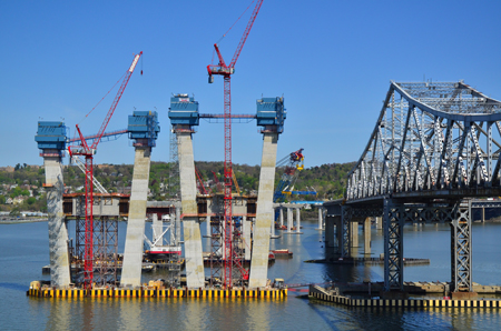
Photo: Andre Markarian
Due to the restricted area in the cable zone in the upper section of each tower, the self-climbing inner forms will be replaced by smaller crane-picked forms. Close coordination will be required between the installation of the stay-in-place steel anchor boxes and concreting of the tower leg walls.
Access between the jump-form frames on each of the H-frame towers is provided by a catwalk. Due to the outward splay and taper of the tower legs, the catwalk has to be extended every few lifts and will reach a maximum length of approximately 30m when the leg reaches lift 18.
To enhance safety and productivity, OM Engineering eliminated the use of ladders in between the main decks in the jump-form system. This was achieved by attaching an external staircase pod to the outside face of the jump-form frame, thereby providing permanent safe access between all working decks.
The lower deck area of the jump-form is usually the most congested area, because this is the level where most of the work in the construction cycle is done – setting rebar cages, closing forms, installing form ties and so on. In addition, the forms hang at this level and they restrict movement when they are open. To improve accessibility, the designer extended the lower deck platforms outwards by 600mm on all sides, hence the lower platform extends beyond the outer limits of the jump-form frame. This allows workers to move around the perimeter of the tower unhindered by open forms and form ties.
“OM Engineering has supplied jump-form systems to the building, industrial tank and bridge building industries and lessons from these different environments have led to safety and productivity improvements,” says OM engineering managing director Oliver Mork. “We do not apply a one-size-fits-all approach to jump-form design, but we often find that an innovative solution in one industry or jurisdiction can be adapted and applied to other industries”.
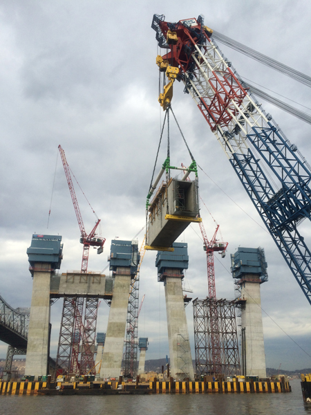
Photo: Andre Markarian
The features and functions of the jump-form system have allowed TZC to rapidly progress construction with all eight tower legs now well above the cross-beams and exceeding 50% completion. Due to the geometry, the tower legs could not be constructed higher than 53m without building the cross-beam to stabilise the legs. In addition to reinforcing the tower legs via post tensioning strand installed through the top and bottom of the beams and through the adjacent towers, the cross-beams will also support the future road decks. TZC originally planned to cast the four, 8.5m tall by 5m wide by 27m long concrete cross-beams in place but there was always the possibility that the weather could potentially slow down construction of the towers to a grinding halt. TZC engineer Andre Markarian recalls wondering: “What if we could precast the four cross-beams off site and set the massive concrete beams in place between the tower legs on falsework?” This is exactly what TZC enacted, subcontracting the casting of the concrete cross-beams to specialist Coastal Precast Systems.
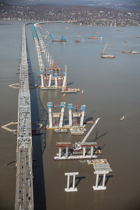
Photo: New York State Thruway Authority
During the late summer and autumn, while TZC was busy progressing the tower legs, CPS was diligently tying rebar, forming and pouring the four concrete cross-beams directly on an 82m-long barge at its facility in Chesapeake Bay, Virginia. By the time TZC was ready to install the beams, CPS floated the barge up the Atlantic coast and to the jobsite. In the winter of 2015-2016, making use of the I Lift NY floating shear-leg crane, TZC set each 680t precast concrete beam 34m above the Hudson River on specially-designed falsework systems. The only work remaining was to tie in the massive beams to the faces of the tower legs. In order to do this, the beams were cast 3m short with rebar projecting out of each end in order to lap splice to couplers cast into the face of the tower legs. Once the closure pours were cast-in place and the post-tensioning strand installed and stressed, the jump-form systems could resume construction.
With the change of season and the onset of warmer weather, TZC expects the first stay cables to be installed early this summer and completion of the tower legs for the first bridge to be complete by late summer.